Eureka AIR delivers breakthrough ideas for toughest innovation challenges, trusted by R&D personnel around the world.

A fiber optic filter device

A technology of optical fiber filtering and optical fiber lines, applied in optics, light guides, optical components, etc., can solve problems such as uneven heating, optical fiber signal attenuation, signal distortion, etc., achieve uniform and effective heating, good heat preservation performance, and actively filter out optical noise Effect

Inactive Publication Date: 2019-07-16
北京天海蓝业科技有限公司
View PDF5 Cites 0 Cited by
  • Summary
  • Abstract
  • Description
  • Claims
  • Application Information

AI Technical Summary

Problems solved by technology

In the prior art, the heating device installed in the noise filter device needs to use air radiation to transfer heat, the heating speed is very slow and uneven, and it is difficult to maintain the stable and normal operation of the optical fiber in harsh environments. The transmitted signal is attenuated so that the signal is distorted
In addition, when the laser is turned on instantly, a strong optical noise signal will be generated, which will further affect whether the optical fiber signal can be transmitted stably when passing through the heated part of the optical fiber, and then whether the signal receiving end can obtain correct and complete transmission of information affects

Method used


Image

  • A fiber optic filter device
  • A fiber optic filter device
  • A fiber optic filter device

Examples


Embodiment 1

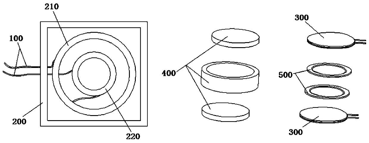
[0027] Such as figure 1 As shown, the present invention provides an optical fiber filtering device, comprising: an optical fiber cable 100, an optical fiber box 200, a heating sheet 300, a heat insulating cotton 400, and a heat-conducting silica gel sheet 500; the outer coiling part 210 and the The inner coiled part 220; the outer coiled part 210 has a storage space for accommodating 100-150 meters of optical fiber in the form of coiling; the optical fiber 100 enters after being wound for 100-150 meters by the outer coiled part The inner coiled part 220; the inner coiled part is wrapped with the heat insulation cotton 400; the inner wall of the heat insulation cotton 400 is attached with the thermal conductive silica gel sheet 500; the heating sheet 300 is laid on the heat insulation Cotton 400 and the heat-conducting silica gel sheet 500; the optical fiber cable 100 is drawn out of the optical fiber box 200 after being wound at the inner coiling part 220, and the coil formed ...

Embodiment 2

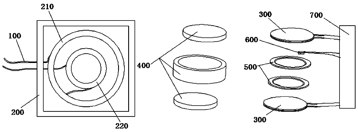
[0036] figure 2 As shown, in this embodiment, on the basis of Embodiment 1, a temperature sensor 600 is also attached to the thermally conductive silica gel sheet 500; a controller 700 is provided on the power supply connected to the heating sheet; the temperature sensor 600 is connected with The controller 700 is connected; when the optical fiber filter device is working, the variation range of the inner coiled part near the working temperature setting value is less than 0.1 degrees Celsius.

[0037] It should be noted that the temperature sensors and controllers used in this embodiment are prior art, so the detailed structures and models of the above temperature sensors and controllers will not be further illustrated and described here.

[0038] Preferably, in a preferred technical solution of this embodiment, the set value of the working temperature is between 24°C and 60°C. The present invention selects the above-mentioned constant temperature interval as the working tem...

Embodiment 3

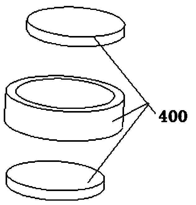
[0041] image 3 As shown, on the basis of the above-mentioned embodiments, the heat insulation cotton of the present invention includes: a heat insulation cylinder made of heat insulation cotton, and two end caps whose shape is adapted to the cross-sectional shape of the inner wall of the heat insulation cylinder ; after the heat insulation cylinder is fastened by the end cover, the inner coil is sealed. The present invention achieves the technical effect of high-efficiency thermal insulation of the inner coiled part by adopting the heat-insulation cotton with the above-mentioned structure.

[0042] Preferably, this embodiment is based on the above embodiments, the thickness of the heat insulation cylinder and the end cap is not less than 10 mm. The present invention can obtain high-quality heat preservation and heat insulation effect by adopting the heat insulation cylinder with the above thickness, and provide strong structural support for creating a constant temperature fi...


PUM


Abstract

The invention discloses an optical fiber filtering device which has functions of actively filtering light noises and uniformly and effectively heating internal disc winding parts. The optical fiber filtering device structurally comprises an optical fiber wire, an optical fiber box, a heating sheet, heat insulation cotton and a heat-conducting silicon gel sheet, wherein the optical fiber box is internally provided with an external disc winding part and an internal disc winding part; the external disc winding part is provided with a storage space for storing the 100m-150m optical fiber wire in a winding manner; after the optical fiber wire is wound for 100m-150m through the external disc winding part, the optical fiber wire enters the internal disc winding part; the internal disc winding part covers the heat insulation cotton; the heat-conducting silicon gel sheet is attached on an inner wall of the heat insulation cotton; the heating sheet is laid between the heat insulation cotton and the heat-conducting silicon gel sheet; after the optical fiber wire is wound in the internal disc winding part, the optical fiber wire is led out of the optical fiber box; and in a winding process, a wire disc formed by the optical fiber wire is in contact with the heat-conducting silicon gel sheet and is uniformly distributed relative to the heat-conducting silicon gel sheet. The optical fiber filtering device has the technical advantages that the heat preservation performance is good after heating, and light pulse with signal interference, caused by the fact that a laser device is started and stopped, can be effectively shielded.

Description

technical field [0001] The invention relates to the technical field of optical fiber filtering, in particular to an optical fiber filtering device. Background technique [0002] The optical fiber in the prior art will carry some optical noise signals due to external influences during signal transmission, and these optical noise signals will affect the clarity of the optical fiber signal during transmission. In order to solve this technical problem, the method of installing a noise filter device at the initial end of optical fiber transmission is adopted in the prior art to achieve the technical effect of reducing optical noise as much as possible. Although the above structure can filter out optical noise to a certain extent, the noise filtering effect still needs to be further improved. The residual optical noise signal still has a certain influence on the transmitted signal, and this effect is more prominent when the laser works instantaneously. . Furthermore, the optimum...

Claims


Application Information

Patent Timeline
Patent Type & Authority Patents(China)
IPC IPC(8): G02B6/44
CPCG02B6/4439G02B6/4452
Inventor 王明陶
Owner 北京天海蓝业科技有限公司
Why Eureka
Eureka Blog
Learn More