
High-tensile-strength power transmission cable

A high tensile strength, power transmission technology, applied in the direction of power cables, power cables including optical transmission components, insulated cables, etc., can solve problems such as large resistance, elevation, irregularities, etc., to improve mechanical strength and avoid delamination , The effect of improving the tensile strength

Inactive Publication Date: 2017-02-22
JIANGSU HENGTONG POWER CABLE
View PDF5 Cites 4 Cited by
  • Summary
  • Abstract
  • Description
  • Claims
  • Application Information

AI Technical Summary

Problems solved by technology

The traditional air blowing method cannot meet the requirements of laying optical fiber composite cables after the optical unit, so the main problem of laying optical fiber composite cables after the optical unit is how to solve the air blowing of the optical unit under the conditions of large resistance, irregularity and long distance Laying problems, the requirements for air blowing laying are also greatly improved

Method used


Image

  • High-tensile-strength power transmission cable
  • High-tensile-strength power transmission cable
  • High-tensile-strength power transmission cable

Examples


Embodiment

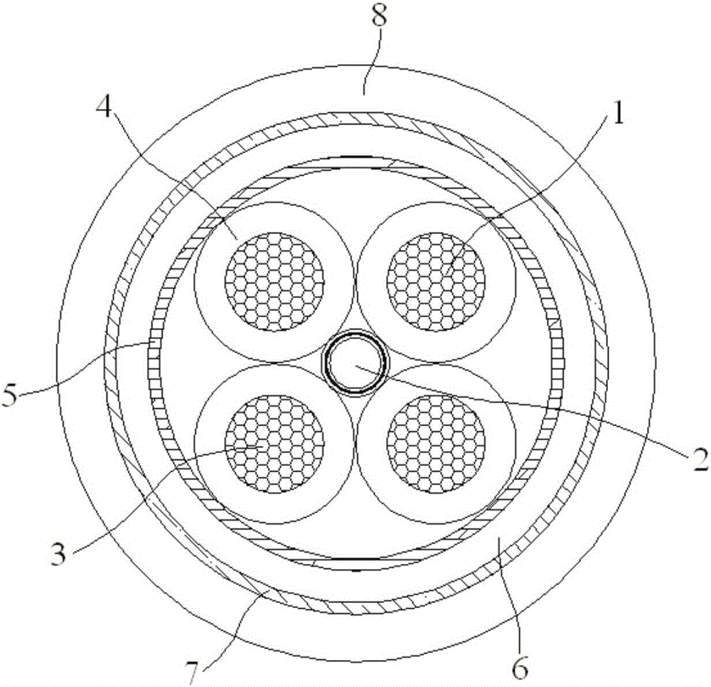
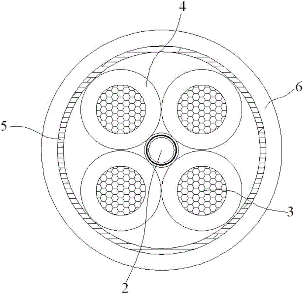
[0021] Embodiment: A power transmission cable with high tensile strength, comprising: 4 circular conductive units 1 and 1 hollow microtube 2 for embedding optical fibers, and the conductor unit 1 includes conductive wire cores 3 sequentially from the inside to the outside 1. The insulating layer 4 coated on the outer surface of the conductive wire core 3, the four circular conductive units 1 are arranged circumferentially along the hollow microtube 2, and a wrapping tape 5 is wrapped around the four circular conductive units 1. The outer surface of the unit 1, the outer surface of the wrapping tape 5 is coated with an inner sheath layer 6, and an armor layer 7 is coated on the outer surface of the inner sheath layer 6, and the outer surface of the armor layer 7 is coated with an outer Sheath layer 8;

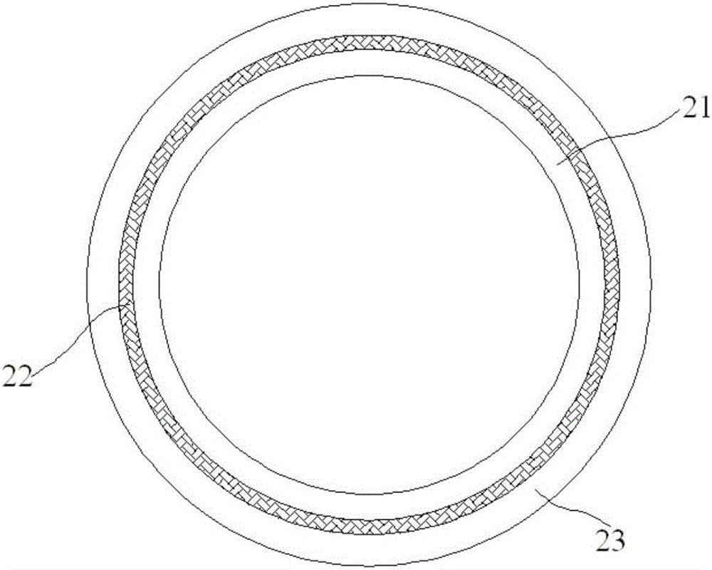
[0022] The hollow microtube 2 is composed of a tensile layer 21, an aramid fiber braided layer 22 and a polyethylene layer 23, and the aramid fiber braided layer 22 is located b...


PUM

PropertyMeasurementUnit
densityaaaaaaaaaa
melt flow indexaaaaaaaaaa
thicknessaaaaaaaaaa

Abstract

The invention discloses a high-tensile-strength power transmission cable comprising four circular conductive units and one hollow micro-tube used for embedding of an optical fiber. Each conductor unit comprises a conductive wire core and an insulating layer which wraps the external surface of the conductive wire core, wherein the conductive wire core and the insulating layer are arranged from inside to outside in turn. The four circular conductive units are arranged along the circumferential direction of the hollow micro-tube. A wrapping tape wraps the external surface of the four circular conductive units. The external surface of the wrapping tape is wrapped by an internal sheath layer. An armored layer wraps the external surface of the internal sheath layer. The external surface of the armored layer is wrapped by an external sheath layer. Maleic anhydride grafted amorphous polyolefin is prepared in a way that amorphous polyolefin, maleic anhydride, lauroyl peroxide and ethylene bisstearamide are put into a double-screw extruder according to the proportion of 100:0.4-3:0.03-1:0.1-0.3 through graft polymerization The situation that common air blowing laying is only suitable for parallel laying can be overcome, air pressure of the air compressor can be increased and finally the bending air blowing laying function can be realized.

Description

technical field [0001] The invention relates to an optical fiber composite cable, in particular to a power transmission cable with high tensile strength. Background technique [0002] Ordinary air-blow laying is horizontal laying, and the micro-cable is blown horizontally into the dedicated preset pipe through mechanical propellers and air compressors. However, for this type of air-blown composite fiber optic cable, the cable cannot be placed horizontally during construction and laying, and it will face various situations such as pipe passing, turning, and hanging, and sometimes even requires direct air blowing on the reel before laying. Laying. The cable is air-blown on the cable reel. During the entire air-blowing laying process, the resistance of the optical unit is greater, and the direction and position of the travel are irregular. The traditional air blowing method cannot meet the requirements of laying optical fiber composite cables after the optical unit, so the ma...

Claims


Application Information

Patent Timeline
Patent Type & Authority Applications(China)
IPC IPC(8): H01B7/18H01B9/00G02B6/44
CPCB32B1/08B32B5/02B32B27/20B32B27/32B32B27/34B32B2262/02B32B2307/54B32B2307/546C08L77/02C08L2203/18C08L2203/20C08L2205/02C08L2205/035G02B6/443G02B6/4432H01B7/18H01B7/1815H01B7/1875H01B9/005C08L77/06C08L23/0823C08L51/06C08K5/18C08K5/526C08K5/103C08L71/02
Inventor 廉果管新元钱江伟万育萍
Owner JIANGSU HENGTONG POWER CABLE
Learn More