Motor rotor cooling structure

A technology of cooling structure and motor rotor, which is applied in cooling/ventilation device, magnetic circuit shape/style/structure, electric components, etc., can solve the problems of limited cooling method of motor, short circuit of motor internal winding, and difficulty in reducing high temperature of motor. Significant cooling effect, reducing safety hazards and reducing energy consumption

Pending Publication Date: 2017-02-22
CHANGCHUN UNIV OF TECH
View PDF10 Cites 11 Cited by
  • Summary
  • Abstract
  • Description
  • Claims
  • Application Information

AI Technical Summary

Problems solved by technology

The current motor cooling methods are limited, and the cooling effect is not obvious, so it is difficult to reduce the high temperature inside the motor
Since the resistivity of the insulating material between the internal windings of the motor will decrease at high temperature, if the temperature reaches a certain limit, the insulator will conduct electricity, short-circuit the internal windings of the motor, and in severe cases, a fire will occur

Method used


Image

  • Motor rotor cooling structure

Examples


Embodiment Construction

[0010] Below in conjunction with accompanying drawing, the present invention is described in further detail:

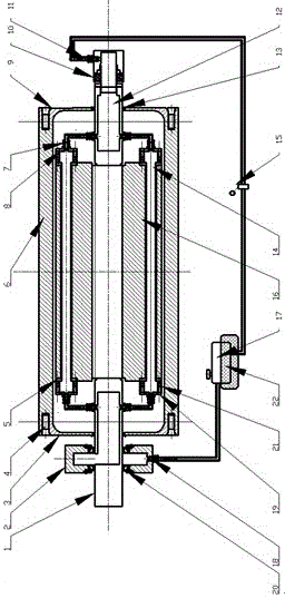
[0011] Motor rotor cooling structure, such as figure 1 As shown, its structure includes: motor rotor shaft 1 with partial holes, oil collector 2, motor front end cover 3, end cover fixing bolt 4, short circuit ring 5, motor stator 6, ferrule type pipe joint 7, outer end of oil ring Cover 8, Motor rear end cover 9, Rotary joint 10, Cooling oil inlet 11, Partial hole motor rotor shaft rear end 12, Rotary bearing 13, Aluminum tube 14, Oil pump 15, Rotor body 16, Oil tank 17, Cooling oil outlet 18. Oil ring fastening bolt 19, skeleton oil seal 20, sealing washer 21, cooling device 22. The partially perforated motor rotor shaft 1 is perforated at the corresponding design position, which is convenient to use the sleeve type pipe joint 7 and the oil pipe to connect with the outer end cover 8 of the oil ring to form a passage, which is convenient for the smooth circulation ...


PUM


Abstract

The invention provides a rotor cooling structure which belongs to the field of motor cooling. A motor rotor is cooled as a whole by circulating pressed cooling oil fluid in the motor rotor. The motor rotor cooling structure comprises a high speed rotary joint, a ferrule-type pipe joint, a motor rotor body, a partially trepanned rotor shaft and the like. The high speed rotary joint comprises a bearing, a sealing ring and an external interface. The ferrule-type pipe joint comprises a ferrule, a nut, a joint body, a combined washer and the like. When aluminium casting is carried out at the corresponding position of the motor rotor body, a dummy shaft is used to cast an aluminum tube at the corresponding position of the rotor body, and a short circuit ring and the aluminum tube cast in the rotor body are cast into a whole body. A blind hole and a screw hole which fixes the ferrule-type pipe joint are arranged in the corresponding position of the partially trepanned rotor shaft. An oil collector comprises an oil collecting tank and a skeleton seal. According to the invention, the overall rotor body is cooled by the cooling oil fluid; the possibility of burning is reduced; the hidden danger of cooling fluid leakage is avoided; the vibration noise of a motor is reduced; and the service life of the motor is prolonged.

Description

technical field [0001] The invention relates to the field of motor cooling, in particular to a squirrel-cage rotor oil cooling structure. Background technique [0002] Now the working current of the motor is large and the speed is high, so the motor itself will generate a lot of heat during the working process. The current motor cooling methods are limited, and the cooling effect is not obvious, so it is difficult to reduce the high temperature inside the motor. Since the resistivity of the insulating material between the internal windings of the motor will decrease at high temperature, if the temperature reaches a certain limit, the insulator will conduct electricity, short-circuit the internal windings of the motor, and in severe cases, a fire will occur. From this point of view, it is very important to design a reasonable cooling structure. [0003] At present, there are two types of cooling structures for most rotors. One is the air-cooling structure, that is, fan blad...

Claims


Application Information

Patent Timeline
Patent Type & Authority Applications(China)
IPC IPC(8): H02K1/32H02K9/197
CPCH02K1/32H02K9/197
Inventor 李绍松崔高健张邦成任海波张袅娜卢晓晖于志新陈国迎何磊胡云峰
Owner CHANGCHUN UNIV OF TECH
Why Eureka
Try Eureka