
Zero-intermediate frequency receiver

A zero-IF receiver and electro-optical modulation technology, applied in the field of communication, can solve the problems of increased module complexity, unbalanced I/Q two-way amplitude, and inability to filter low-frequency components, so as to reduce I/Q unbalanced, large Effect of spurious-free dynamic range, stable performance, and specifications

Inactive Publication Date: 2017-02-22
BEIJING UNIV OF POSTS & TELECOMM +1
View PDF5 Cites 6 Cited by
  • Summary
  • Abstract
  • Description
  • Claims
  • Application Information

AI Technical Summary

Problems solved by technology

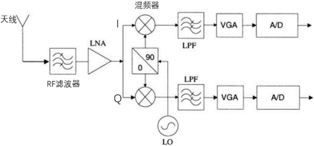
[0004] But these zero-IF receivers have many problems such as poor isolation and DC offset
There is leakage of local oscillator and radio frequency signal in the mixer, self-mixing produces useless DC component, which deteriorates the signal, makes the subsequent amplifying circuit saturated, and cannot amplify the signal
Narrowband low frequency, existing electronic mixing technology cannot handle sufficiently wideband and high frequency signals
The dynamic range is poor, and the zero-IF signal is also at low frequency, and all low-frequency components cannot be filtered. Therefore, the sensitivity and dynamic range of the zero-IF receiver are relatively poor
I / Q imbalance, because the gains of the mixer and the amplifier are not exactly the same, so that there is an amplitude imbalance between the I / Q two channels, and the difference between the I / Q two local oscillator signals cannot reach an absolute 90 degrees, making the I / Q two channels There is a phase imbalance in the path, and these two I / Q imbalances will affect the demodulation of the signal. These problems seriously affect the performance parameters of the zero-IF receiver, making it difficult to apply in high-index and strict requirements.
[0005] At the same time, the performance development of traditional radio frequency receivers has reached the limit so far, and the electronic characteristics of the microwave devices used in them limit the frequency band and bandwidth that the mixer can handle
Moreover, in order to obtain higher performance indicators such as processing bandwidth, isolation, intermodulation rejection, and image rejection, traditional microwave receivers need to carry out several stages of frequency conversion and filter design, which not only increases the complexity of the entire module, but also does not improve much of the indicators. Space

Method used


Image

  • Zero-intermediate frequency receiver
  • Zero-intermediate frequency receiver
  • Zero-intermediate frequency receiver

Examples


Embodiment Construction

[0021] The following will clearly and completely describe the technical solutions in the embodiments of the present invention with reference to the accompanying drawings in the embodiments of the present invention. Obviously, the described embodiments are only some, not all, embodiments of the present invention. Based on the embodiments of the present invention, all other embodiments obtained by persons of ordinary skill in the art without making creative efforts belong to the protection scope of the present invention.

[0022] Combine below image 3 Specific embodiments of the present invention are described.

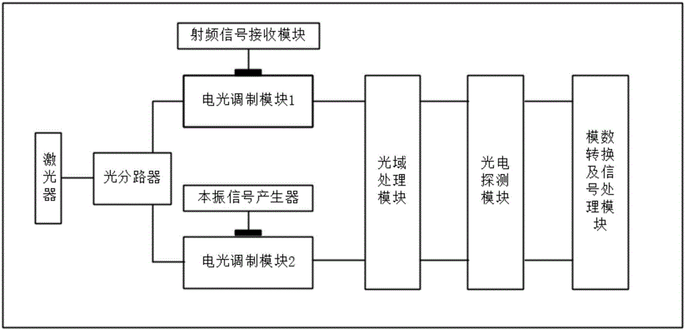
[0023] The zero-IF receiver of the present invention mainly includes: a laser, an optical splitter, a first electro-optic modulation module, a second electro-optic modulation module, a radio frequency signal receiving module, a local oscillator signal generator, an optical domain processing module, a photoelectric detection module and a module. A digital conversion an...


PUM


Abstract

The invention discloses a zero-intermediate frequency receiver, relates to the technical field of communications, and aims to solve the problems of narrow band, low frequency, poor isolation, I / Q imbalance and low dynamic range in an existing zero-intermediate frequency receiver. In the zero-intermediate frequency receiver disclosed by the invention, a laser is connected with an optical divider; the optical divider is respectively connected with a first electro-optical modulation module and a second electro-optical modulation module; a radio frequency signal receiving module is connected with the first electro-optical modulation module; a local oscillation signal generator is connected with the second electro-optical modulation module; the first electro-optical modulation module and the second electro-optical modulation module are connected with a raster processing module; the raster processing module is connected with a photoelectric detection module; and the photoelectric detection module is connected with an analog-to-digital conversion and signal processing module.

Description

technical field [0001] The invention relates to the technical field of communication, in particular to a zero-IF receiver. Background technique [0002] Receivers are an integral part of communication systems. With the development of communication systems, the traditional superheterodyne receiver structure is difficult to integrate on a chip and the carrier frequency variability is poor, so it is difficult to meet the requirements of high integration, wide bandwidth and flexible carrier configuration in practical applications Therefore, the zero-IF receiver structure has entered the field of vision of engineers. The zero-IF receiver structure is a technology that directly down-converts the useful signal to the baseband, realizes zero intermediate frequency, completely eliminates the problem of image response, and is easy to achieve high integration on the chip. At the same time, the carrier signals of various frequencies can be flexibly configured by changing the frequency...

Claims


Application Information

Patent Timeline
Patent Type & Authority Applications(China)
IPC IPC(8): H04B1/16
CPCH04B1/16
Inventor 李建强吕强郑月肖佳尹飞飞戴一堂徐坤
Owner BEIJING UNIV OF POSTS & TELECOMM
Learn More