
Manufacturing equipment of material to be forged and method for manufacturing material

A manufacturing device and manufacturing method technology, applied to the manufacturing device and its manufacturing field of raw materials for forging processing, capable of solving problems such as iron oxide layer residue and product defects, achieving great effects and improving production efficiency

Active Publication Date: 2017-03-01
塩川正兴
View PDF9 Cites 1 Cited by
  • Summary
  • Abstract
  • Description
  • Claims
  • Application Information

AI Technical Summary

Problems solved by technology

It may be removed in subsequent machining processes such as cutting and grinding, but if only grinding is performed, there will be the following problem: the iron oxide layer will remain and the product will become a defective product

Method used

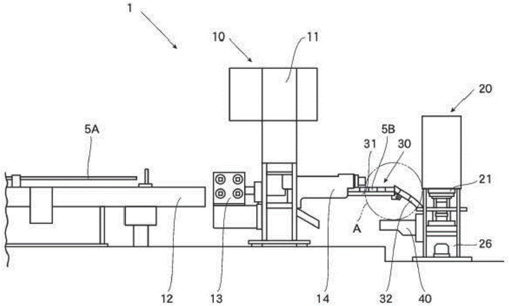
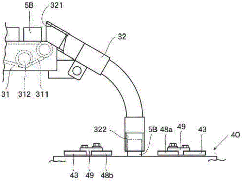
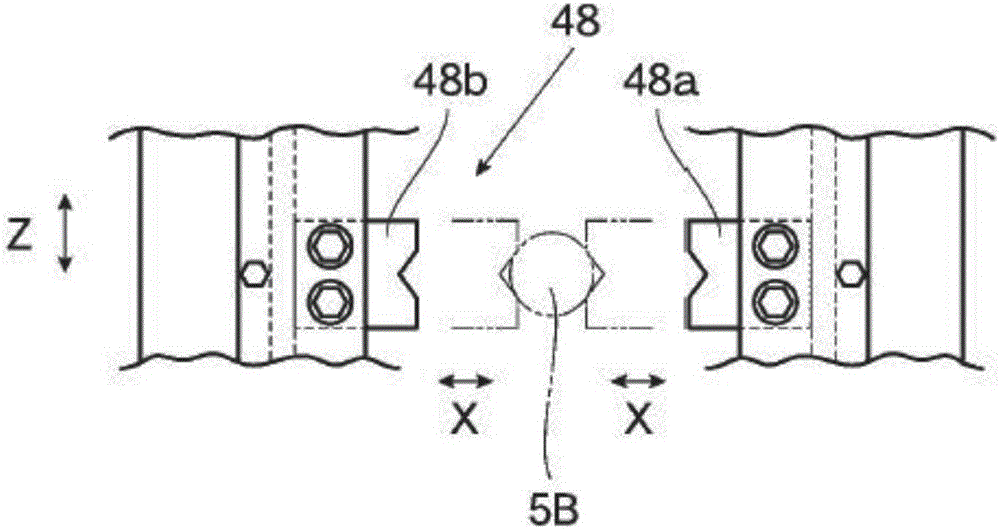

Image

  • Manufacturing equipment of material to be forged and method for manufacturing material
  • Manufacturing equipment of material to be forged and method for manufacturing material
  • Manufacturing equipment of material to be forged and method for manufacturing material

Examples


example 2

[0170] Figure 12 Example 2 of the raw material for forging process manufactured by the said manufacturing apparatus 1, ie, the raw material 5c for forging process is shown. After pressurizing a pair of dies with only the R-shaped die surface to produce the raw material for forging processing, it becomes as follows Figure 12 the shape shown. The forging raw material 5c of Example 2 also does not have sharp corners, so no problem arises.

example 3

[0172] Figure 13 The example 3 of the raw material for forging process manufactured by the said manufacturing apparatus 1, ie, the raw material 5d for forging process is shown. Using the pair of molds 20A, pressurization is performed under conditions lower than the pressurization conditions for the forging raw material 5 of Example 1, and after the forging raw material is manufactured, it becomes as follows Figure 13 the shape shown. In the central part, there remains a concave part 5d1 in which the cutting surface is in a concave state after being cut by a cutting machine without pressure, but there is no problem due to the shape.

[0173] [Example 4 of raw materials for forging processing]

[0174] Figure 14The example 4 of the raw material for forging process manufactured by the manufacturing apparatus 1 of the raw material for forging process, ie, the raw material 5e for forging processing is shown. Utilizing a pair of molds formed with only the R-shaped mold surfac...


PUM


Abstract

The invention relates to manufacturing equipment for forging processing material and a manufacturing method for same. The manufacturing equipment comprises a chamfering device. The chamfering device is installed at the neighborhood of a cutter cutting rod-shape material in the predetermined length and produces the cutting material, and performs the chamfering when sides of a pair of modes are pressed on corner angles of the cut raw material. The pair of molds comprises one mold forming a mold surface for a chamfer on one side and the other mold forming a mold surface for another chamfer on the other side. The one chamfer presses one corner angle part of the cut raw material to form a regulated surface with a cross section shape; and the other chamfer presses the other corner angle of the cut raw material to form another regulated surface with a cross section shape. The pair of molds is in a structure that upon chamfering, the peripheral part of one mold is embedded into a guide inner peripheral part of the other mold. Production efficiency can be improved and forging quality can be enhanced.

Description

technical field [0001] The present invention relates to a manufacturing device and a method for manufacturing a forging raw material having a surface of a predetermined shape formed at an edge of a cut raw material, and a method for manufacturing a forging raw material. More specifically, the present invention relates to a manufacturing device and a method for manufacturing raw materials for forging, in which corners of cut raw materials obtained by cutting rod-shaped raw materials into predetermined lengths with a cutting machine are chamfered to a predetermined length. Shaped surface, so as to manufacture raw materials for forging processing. Background technique [0002] In the past, automotive-related parts such as spur gears, bevel gears, constant velocity joints, and clutch plates were generally forged products. The material for forging used in the manufacture of these forged products is a material (eg, a steel cylinder) obtained by cutting a bar-shaped material (eg, ...

Claims


Application Information

Patent Timeline
IPC IPC(8): B21J1/00
CPCB21J1/00B21J1/02B21J5/02B21J13/02
Inventor 塩川正兴
Owner 塩川正兴
Learn More