Real-time dynamic testing circuit for anti-fuse FPGA microprobe

A dynamic testing, real-time dynamic technology, applied in the field of integrated circuits

Inactive Publication Date: 2017-03-01
华晋书
View PDF0 Cites 4 Cited by
  • Summary
  • Abstract
  • Description
  • Claims
  • Application Information

AI Technical Summary

Problems solved by technology

With the rapid development of integrated circuits, the integration of chips is increasing day by day, the complexity of circuit design is increasing, and the requirements for testing integrated circuits are getting higher and higher

Method used


Image

  • Real-time dynamic testing circuit for anti-fuse FPGA microprobe
  • Real-time dynamic testing circuit for anti-fuse FPGA microprobe
  • Real-time dynamic testing circuit for anti-fuse FPGA microprobe

Examples


Embodiment Construction

[0013] In order to make the purpose, technical solutions and advantages of the embodiments of the present invention clearer, the technical solutions in the embodiments of the present invention will be clearly and completely described below in conjunction with the drawings in the embodiments of the present invention. Obviously, the described embodiments It is a part of embodiments of the present invention, but not all embodiments. Based on the embodiments of the present invention, all other embodiments obtained by persons of ordinary skill in the art without creative efforts fall within the protection scope of the present invention.

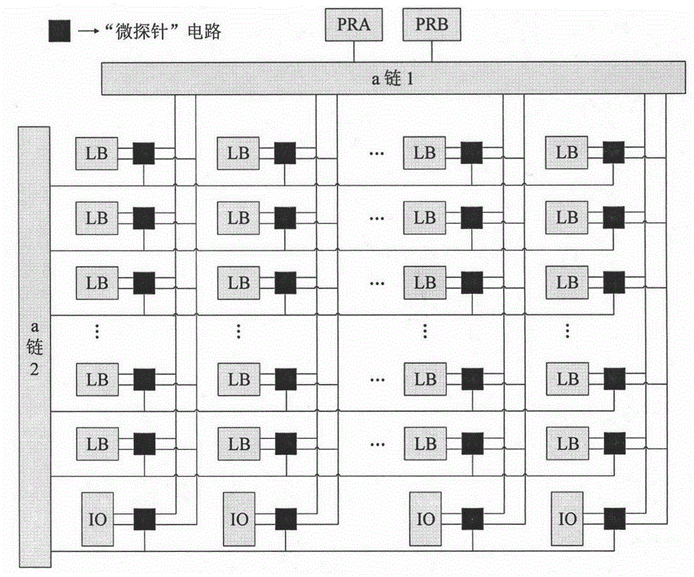
[0014] figure 1 It is a block diagram of the dynamic test circuit system array of the present invention. In the logic array of the antifuse FPGA, the output terminal of each logic module LB has a detection circuit structure for detecting the output signal of the logic module, which is represented by a black square pattern in the figure. Since th...


PUM


Abstract

The invention belongs to the integrated circuit field, and relates to a real-time dynamic testing circuit for anti-fuse FPGA microprobe. In particular, through this form of structure, it is not only possible to help achieve the digital function of a chip, but also to effectively ensure the qualification rate of chip manufacturing. And the microprobe can enable users to detect any node inside the circuit in the application stage after the anti-fuse FPGA programming is completed so as to determine whether the function of the chip is correct or not. The structure of such dynamic testing circuit occupies few chip resources and involves only a very few digitalized circuit modules. With the conception of simulated design, the circuit structure can be simplified; the performance of the circuit can be optimized; accordingly, the circuit can work normally and efficiently.

Description

technical field [0001] The invention belongs to the field of integrated circuits, and relates to a microprobe real-time dynamic test circuit for antifuse FPGA, especially through this structure, the test mode of antifuse FPGA can be made more flexible and changeable, greatly improving the performance of the chip. For the test efficiency and testability, the microprobe design should have high coverage and can detect any circuit node. Background technique [0002] FPGA is Field Programmable Gate Array, which is a product of further development on the basis of programmable devices such as PAL, GAL, and CPLD. It emerged as a semi-custom circuit in the field of application-specific integrated circuits (ASIC), which not only solves the shortcomings of custom circuits, but also overcomes the shortcomings of the limited number of original programmable device gates. There are abundant wiring resources inside the FPGA chip, and the wiring resources connect all the units inside the FP...

Claims


Application Information

Patent Timeline
IPC IPC(8): G01R31/28
Inventor 华晋书
Owner 华晋书
Why Eureka
Try Eureka