Electrical energy storage element, method and apparatus for producing said electrical energy storage element

A technology for electric energy storage and components, which is applied in the direction of electrical components, battery electrodes, and final product manufacturing, and can solve problems such as energy density reduction

Inactive Publication Date: 2017-03-01
FRAUNHOFER GESELLSCHAFT ZUR FOERDERUNG DER ANGEWANDTEN FORSCHUNG EV +2
View PDF8 Cites 4 Cited by
  • Summary
  • Abstract
  • Description
  • Claims
  • Application Information

AI Technical Summary

Problems solved by technology

[0002] Conventional lithium battery cells (circular, prismatic or flat cells with molded caps with metal casings) were previously used resulting in reduced energy density at the system level

Method used


Image

  • Electrical energy storage element, method and apparatus for producing said electrical energy storage element
  • Electrical energy storage element, method and apparatus for producing said electrical energy storage element
  • Electrical energy storage element, method and apparatus for producing said electrical energy storage element

Examples


example 1

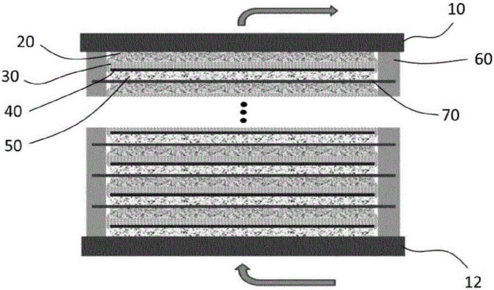
[0062] An electrical energy storage element according to the invention can be manufactured using an aluminum conductive carrier film 70 having a thickness of 15 μm and a width of 100 mm.

[0063] To manufacture the cathode 20, coating was carried out by a roll-to-roll process using a suspension of LNMO in N-methyl-2-pyrrolidone (NMP) on one side of the support film. The composition of the cathode 20 thus obtained was 92 wt.% LNMO, 4 wt.% conductive additive and 4 wt.% PVDF. In this respect, obtain 50.6Ah / m 2 surface capacity. Apply intermittently.

[0064] To produce the anode 50 , a suspension of LTO in NMP is used on the other side of the carrier film 70 in a second coating step. The composition of the resulting anode was 92 wt.% LTO, 4 wt.% conductive additive and 4 wt.% PVDF. In this respect, obtain 52.9Ah / m 2 surface capacity. Apply intermittently.

[0065] The dry electrode strip, coated on both sides with active anode material and cathode material respectively, w...

example 2

[0075] To produce a stack of electrochemical cells, the bottom plate 12 is clamped into a fixing device for fixing the plate from below. The electrodes are provided and placed on the bottom plate 12 with the aid of vacuum tongs in such a way that the coated surfaces face each other. Thereafter, the environment was evacuated to a pressure of 20 mbar, and the electrodes were subsequently pressed onto the base plate 12 by a punch press with a compression force of 10 kPa. In this process, the two-component adhesive is heated to 80°C by a heat carrier for curing.

[0076] Subsequently, the next electrode is provided and placed; the environment is evacuated; the electrode is pressed; and the adhesive is heated. These steps were repeated until 351 electrodes were stacked on the base plate.

[0077] In the final steps, the top plate 10 is provided by grippers and placed on the stack; the environment is then evacuated; the top plate 10 is pressed; and the adhesive is heated.

example 3

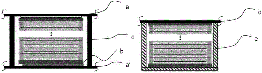
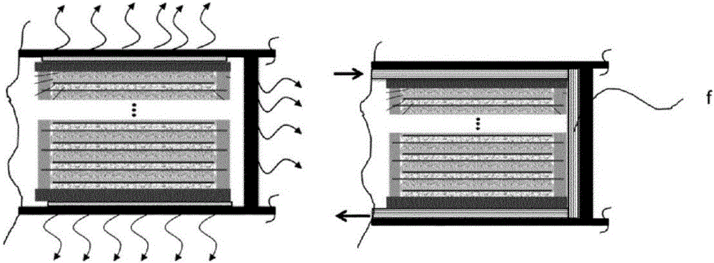
[0079] figure 2 A possible installation on the lower body of the vehicle is shown on the left. a = middle vehicle body; a' = lower vehicle body; b = heat-conducting insulating layer, joint; c = vehicle support; on the right side the mounting on the underside of the solar module is shown: d = solar module; e = module frame.


PUM

PropertyMeasurementUnit
thicknessaaaaaaaaaa
widthaaaaaaaaaa

Abstract

In the electrical energy storage element according to the invention, a plurality of electrochemical cells, which are each formed with a cathode and an anode as electrodes and with an electrolyte, are arranged in a manner stacked one above the other. On one side, said electrochemical cells are surrounded by a cover plate which is formed from an electrically conductive material, in particular aluminium, and on the opposite side are surrounded by a base plate which is formed from an electrically conductive material, in particular aluminium. The base plate is coated with a cathode or an anode, and the cover plate is coated in a complementary manner with an anode or cathode. The anodes and cathodes are each formed on opposite surfaces of an electrically conductive carrier foil or film which is preferably composed of aluminium, copper, steel or electrically conductive plastic. An outer circumferential edge which is free of electrode material is present on the carrier foil or film, said edge connecting adjacent electrochemical cells to one another by means of a sealing and adhesive means such that they are hermetically sealed off from one another and from the surrounding area. The anodes are formed from a lithium titanate (LTO) having a spinel structure, and the high-voltage cathodes are formed from a lithium nickel manganate (LNMO) having a spinel structure or lithium phosphates (LP) in an olivine structure. A separator layer is in each case provided between the electrolyte and an electrode of an electrochemical cell in the case of a gel-like electrolyte, and no separator is provided in the case of a solid electrolyte.

Description

technical field [0001] The present invention relates to a large-scale, flat, securely constructed electrical energy storage element with specific cytochemical technology for bipolar electrode construction including a monolithic housing. The invention also relates to a method and a device for manufacturing these electrical energy storage elements. Background technique [0002] Conventional lithium battery cells (circular, prismatic, or flat cells with molded covers) with metal casings were previously used resulting in reduced energy density at the system level. Bipolar batteries are also known. [0003] Typically, these cells are connected to each other in modules (approximately 60V, approximately 12 cells). The individual modules are then connected to form a high-voltage (HV) energy storage and, together with peripheral sensor systems, monitoring systems (energy storage management systems), cooling systems and housings, form a safe energy storage element. For example, int...

Claims


Application Information

Patent Timeline
Patent Type & Authority Applications(China)
IPC IPC(8): H01M10/0585H01M10/52H01M50/159H01M50/164
CPCH01M10/0585H01M10/52H01M50/164H01M10/48H01M50/159Y02E60/10Y02P70/50H01M10/63H01M10/6556H01M10/0468H01M10/0565H01M4/483H01M4/505H01M4/525H01M4/5825H01M2300/0085
Inventor 马雷克·沃尔特克里斯蒂安·尼克罗维斯基乌韦·帕特奇迈克尔·罗舍尔托马斯·埃切尔梅耶丹尼尔·蒂特尔迈克尔·克劳斯
Owner FRAUNHOFER GESELLSCHAFT ZUR FOERDERUNG DER ANGEWANDTEN FORSCHUNG EV
Why Eureka
Try Eureka