Method for automatically capturing microball in optical tweezer system

An automatic capture and microsphere technology, which is applied to capture objects visible under the microscope, acquire/recognize the direction of microscopic objects, instruments, etc., can solve the problems of not many, limited observation field of view and depth of field, difficulty in capturing particles, etc., and achieve improved stability performance, improve capture efficiency, and eliminate hysteresis

Active Publication Date: 2017-03-08
TIANJIN UNIV
View PDF3 Cites 14 Cited by
  • Summary
  • Abstract
  • Description
  • Claims
  • Application Information

AI Technical Summary

Problems solved by technology

And it is more aimed at the motion control algorithm of larger particles such as cells with a larger field of view, and there are not many algorithms required for measurement applications
For the optical tweezers system used for force spectrum measurement, the required particle diameter is smaller, generally around 1-2um; the required optical trap has a higher stiffness, which often needs to reach 0.5pn / nm, which means that the used objective lens With a higher numerical aperture, the observation field of view and depth of field become limited, which ultimately makes the phenomenon of particle recapture more likely to occur
At the same time, due to the increase in stiffness, higher laser power is required, which also leads to a more obvious heating effect in the sample cell and leads to convection of the liquid in the sample cell
In addition to Brownian motion, particles are also affected by convection in the liquid environment, making it more difficult to capture particles in a targeted manner

Method used


Image

  • Method for automatically capturing microball in optical tweezer system
  • Method for automatically capturing microball in optical tweezer system
  • Method for automatically capturing microball in optical tweezer system

Examples


Embodiment Construction

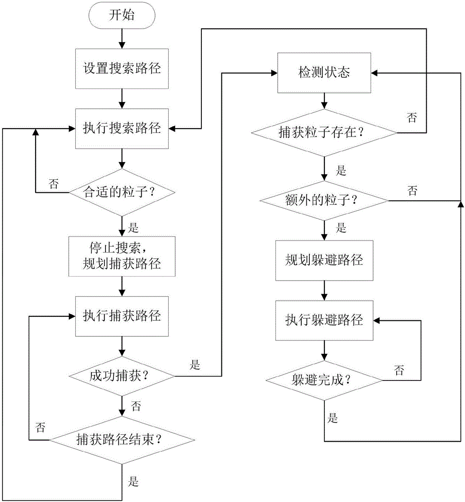
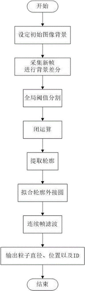
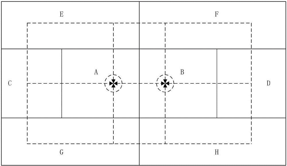
[0042] The method for automatically capturing microspheres based on the optical tweezers system of the present invention will be described in detail below in conjunction with the embodiments and accompanying drawings.

[0043] The test system for this method uses Figure 4 The shown dual optical tweezers system includes a dual optical tweezers generation module, an illumination module, an image acquisition module and a stage control module. The dual optical tweezers generation module adopts single laser (1064nm) beam splitting and high numerical aperture objective lens to converge to generate light traps; the illumination module adopts transmission type coaxial uniform illumination, the illumination light source adopts LED with a wavelength of 780nm, and the illumination optical path and the main optical path adopt dichroism The imaging module uses the DCC1545M COMS camera of Thorlabs in the United States, and the sample displacement platform uses the piezoelectric controller ...


PUM


Abstract

The invention relates to a method for automatically capturing a microball in an optical tweezer system. The method comprises the steps of setting an initial image background; presetting a path, and controlling a micron displacement table to perform a search according to the path; processing each frame of image, and when the microball exists in a view field, outputting the position, the diameter and an ID feature of the microball; after the feature of the microball in the view field is obtained, interrupting the search path to generate a capture path, and performing PI closed-loop control on particles according to a planned path until the particles are successfully captured, otherwise, returning to the search path again for performing the search; judging whether the particles are successfully captured or not; and when other excess particles occur near the captured particles, generating an avoidance path. According to the method, the microball capture efficiency can be greatly improved.

Description

technical field [0001] The invention relates to a microsphere automatic capture method applied to an optical tweezers measurement and test system. In particular, it relates to a method for automatic identification and capture of microspheres under narrow field of view and low depth of field imaging. Background technique [0002] Based on the mechanical effect of light, optical tweezers technology can capture and manipulate micron and nanoscale particles, and measure the applied force. It has the characteristics of non-contact, non-damage and high precision, and is widely used in biological single molecules, cells, etc In the field of measurement, it has greatly promoted the development of quantitative biology. The optical tweezers technology mainly uses a highly focused laser beam to generate a three-dimensional potential well to attract tiny particles, and calculates the corresponding force by measuring the distance between the microsphere and the center of the optical tra...

Claims


Application Information

Patent Timeline
Patent Type & Authority Applications(China)
IPC IPC(8): G06K9/00G06K9/40G06K9/46G06K9/62
CPCG06V20/693G06V20/695G06V10/30G06V10/44G06V10/752
Inventor 苏晨光胡春光云泽霖王思蓉李宏斌胡晓东胡小唐
Owner TIANJIN UNIV
Why Eureka
Try Eureka