Constant current control system
A technology of constant current control and controller, applied in control/regulating systems, regulating electrical variables, instruments, etc., can solve the problems of high power and short life of the voltage drop regulator, reduce current, reduce heat consumption, The effect of increasing the rate of ascent
- Summary
- Abstract
- Description
- Claims
- Application Information
AI Technical Summary
Problems solved by technology
Method used
Image
Examples
Embodiment 1
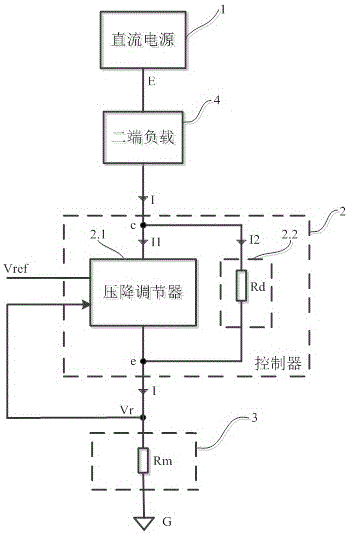
[0020] A constant current control system, including a DC power supply 1 with a voltage E to the loop ground G, a DC power supply 1 according to the input voltage value V r To adjust the voltage V across c and e ce A controller 2, a two-terminal galvanometer 3, and a two-terminal load 4; it is characterized in that: the two-terminal load 4, the two ends of c and e of the controller 2 and the two-terminal galvanometer 3 are connected to the DC power supply 1 The voltage E and the loop ground G are connected in series to form a loop with a current I; the controller 2 is composed of an adjustable voltage V at both ends of c and e ce The pressure drop regulator 2.1 and a resistance value R connected in parallel at both ends of c and e d The shunt resistor 2.2 is composed; the voltage drop regulator 2.1 is based on the input voltage value V r To adjust the voltage V across c and e ce ; The shunt resistor 2.2 flows through the current I 2 =V ce / R d , and make the corresponding...
Embodiment 2
[0022] This embodiment is basically the same as Embodiment 1, and the special features are as follows:
[0023] The two-terminal current detector 3 is a resistance fixed to R m The resistance of the current I produces a current-sensing voltage V m =R m ×I; the voltage drop regulator 2.1 will sense the current voltage V m As the input voltage value V r and with a value of V ref =R m ×I C Compared with the reference voltage, the drop regulator 2.1 increases or decreases the voltage V across c and e ce Make the sense voltage V m =R m The value of ×I is reduced or increased to achieve the current I equal to I C value for constant current control, here I C It is the constant current value that is expected to be achieved.
[0024] The resistance value R of the shunt resistor 2.2 d The internal resistance of the two-terminal load 4 is R L and loop current I=I C The following relationship should be satisfied:
[0025]
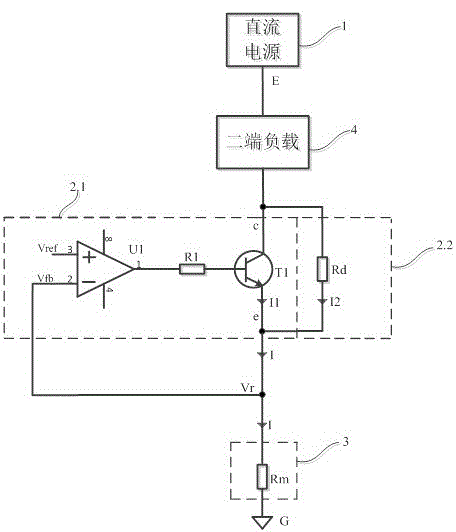
[0026] Such as figure 2 As shown, when one en...
Embodiment 3
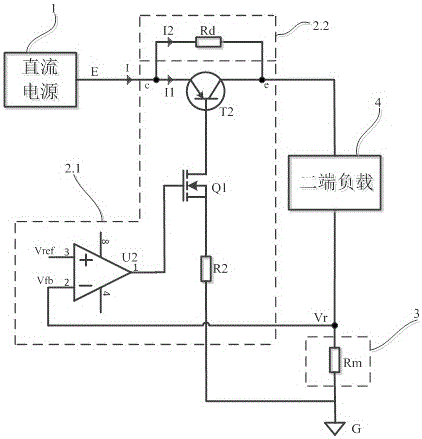
[0029] The operational amplifier is used in the voltage drop regulator 2.1 of the controller 2. Due to the "common mode" characteristic of the operational amplifier, the potentials of the non-inverting input terminal and the inverting input terminal are almost equal, that is, the No. 2 connection of the operational amplifier U1 (or U2) The potential of the head to the loop ground G is almost equal to the voltage drop of the No. 3 connector of the operational amplifier U1 (or U2) to the loop ground G. Then, since the base current of transistor T1 (or transistor T2) is very small, the constant current value I C The size of depends only on the value of V ref The ratio of the reference voltage to the two-terminal current detector 3, that is, the constant current value I C =V ref / R m , which is the principle of constant current control system to achieve constant current control.
[0030] The resistance value R of the shunt resistor 2.2 d The internal resistance of the two-ter...
PUM
 Abstract
Description
Claims
Application Information
 - R&D
- Intellectual Property
- Life Sciences
- Materials
- Tech Scout
- Unparalleled Data Quality
- Higher Quality Content
- 60% Fewer Hallucinations
Browse by: Latest US Patents, China's latest patents, Technical Efficacy Thesaurus, Application Domain, Technology Topic, Popular Technical Reports.
© 2025 PatSnap. All rights reserved.Legal|Privacy policy|Modern Slavery Act Transparency Statement|Sitemap|About US| Contact US: help@patsnap.com


