Supercharge Your Innovation With Domain-Expert AI Agents!

Horizontal omnidirectional high-gain vertical polarization array dipole antenna

A vertically polarized, dipole antenna technology, applied in antennas, antenna arrays, resonant antennas, etc., can solve the problems of volume, weight, and the inability to adapt to gain indicators, achieve small size, high volume, and improve antenna efficiency and gain. Effect

Pending Publication Date: 2017-03-15
SHENZHEN FAST PRECISION TECH CO LTD
View PDF3 Cites 4 Cited by
  • Summary
  • Abstract
  • Description
  • Claims
  • Application Information

AI Technical Summary

Problems solved by technology

[0002] At present, as far as antenna technology is concerned, the miniaturization and diversification of indoor ground relays for CPE terminal equipment and satellite communications and indoor and outdoor base station antennas for mobile communications are signs leading the trend towards the era of data and informationization. In the future, CPE and The indoor and outdoor applications of satellite communication and mobile communication in the era of 4G and 5G have huge market potential. In order to meet the technical requirements of diversification, multi-objective, deep-level and wide coverage, the miniaturization, small size, light weight and horizontal Omni-directional high-gain puts forward new requirements, and the existing omni-directional array antennas are basically unable to meet this requirement in terms of size, weight, and gain indicators.

Method used


Image

  • Horizontal omnidirectional high-gain vertical polarization array dipole antenna
  • Horizontal omnidirectional high-gain vertical polarization array dipole antenna
  • Horizontal omnidirectional high-gain vertical polarization array dipole antenna

Examples


Embodiment Construction

[0035] In order to describe the technical content, structural features, achieved goals and effects of the present invention in detail, the following will be described in detail in conjunction with the embodiments and accompanying drawings.

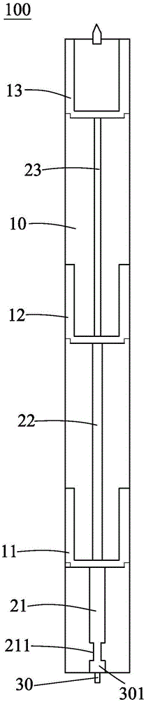
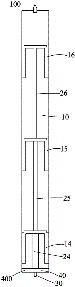
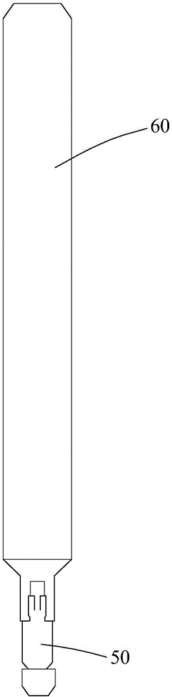
[0036] refer to Figure 1 to Figure 2 , the present invention discloses a horizontal omni-directional high-gain vertically polarized array dipole antenna 100, including a PCB board 10, antenna oscillators 11-16, microstrip transmission lines 21-26, a jacket 60, and a 50-ohm feeding coaxial line 30 and connector 50.

[0037] refer to Figure 1 to Figure 2 , in the first embodiment, the antenna dipole includes 3 pairs of dipole array dipoles 11-16, and three dipole array dipoles 11-13 are arranged at a certain interval from bottom to top on the front of the PCB board 10, and the feeder transmission line The formed first group of microstrip transmission lines is arranged on the front side of the PCB board 10, and the dipole array oscillator...


PUM


Abstract

The invention discloses a horizontal omnidirectional high-gain vertical polarization array dipole antenna, which comprises a PCB, N pairs of dipole array oscillators, microstrip transmission lines, micro-short width lines and reverse longitudinal width lines, a feed coaxial line, a connector, external sleeves, crimping sheets and bolts, wherein the micro-short width lines and the reverse longitudinal width lines are coupled to a reverse first-stage dipole array oscillator to form a micro-short coupling balun converter and a longitudinal coupling balun converter, and have a phase compensation function of exiting oscillator current; one end of the 50ohm feed coaxial line is electrically connected with the antenna through the crimping sheets in a welding manner and the other end is electrically connected with the connector. A balun transformation, impedance transformation, phase difference compensation and secondary coupling excitation integration technology is used for the first time, and the international technical difficulties of the horizontal omnidirectional high-gain elongated planar printed array antenna are overcome. By a crimping technology of the feed coaxial line, the coupling degree of each antenna oscillator is improved, the consistency and the stability of the antenna are strengthened and the service life of the antenna is prolonged. The horizontal omnidirectional high-gain vertical polarization array dipole antenna is simple in structure, simple in production, moderate in cost and convenient to use.

Description

technical field [0001] The present invention is applicable to WIFI terminal equipment (CPE), space docking conversion equipment for 4G-LTE and WIFI data transmission, indoor ground relay system for satellite communication, mobile communication indoor base station antennas of various frequency bands, and miniaturization of mobile communication outdoor base station antennas equipment. GPS ground data receiving and processing relay equipment, miniaturized military field communication equipment, etc. Background technique [0002] At present, as far as antenna technology is concerned, the miniaturization and diversification of indoor ground relays for CPE terminal equipment and satellite communications and indoor and outdoor base station antennas for mobile communications are signs leading the trend towards the era of data and informationization. In the future, CPE and The indoor and outdoor applications of satellite communication and mobile communication in the era of 4G and 5G...

Claims


Application Information

Patent Timeline
IPC IPC(8): H01Q1/38H01Q1/50H01Q9/18H01Q21/00
CPCH01Q1/38H01Q9/18H01Q21/0006H01Q21/0075
Inventor 祝峰
Owner SHENZHEN FAST PRECISION TECH CO LTD
Features
  • R&D
  • Intellectual Property
  • Life Sciences
  • Materials
  • Tech Scout
  • Unparalleled Data Quality
  • Higher Quality Content
  • 60% Fewer Hallucinations
Learn More