Melting furnace for founding high-volatility-component glass

A melting furnace and melting technology, applied in the direction of glass production, electric furnace, furnace type, etc., can solve the problem that it is easy to be brought into the clarification area of ​​the melting furnace, or even the forming part, the glass melting furnace has not been seen, and the quality of the surface layer of the product is lost. , to achieve the effect of reducing the investment in kiln construction, avoiding the fluctuation of design material components, reducing the loss of raw materials and the discharge of pollutants

Active Publication Date: 2017-03-22
江苏华东耀皮玻璃有限公司
View PDF6 Cites 8 Cited by
  • Summary
  • Abstract
  • Description
  • Claims
  • Application Information

AI Technical Summary

Problems solved by technology

[0008] At present, in large-scale melting furnaces, it is generally adopted to install cooling water pipes at the neck to block the scum floating on the glass liquid surface. Although this technology is effective, it is relatively limited in solving the problem of flying materials in the flame space. The piles on the surface of the molten glass are easily brought into the clarification zone of the melting furnace due to fluctuations in the operating conditions of the furnace, and even the forming part, leaving serious quality defects such as s

Method used


Image

  • Melting furnace for founding high-volatility-component glass
  • Melting furnace for founding high-volatility-component glass

Examples


Embodiment Construction

[0037] In order to enable those skilled in the art to better understand the technical solutions in the present application, the technical solutions in the embodiments of the present application will be clearly and completely described below in conjunction with the drawings in the embodiments of the present application. Obviously, the described The embodiments are only some of the embodiments of the present application, but not all of them. Based on the embodiments in this application, all other embodiments obtained by persons of ordinary skill in the art without making creative efforts shall fall within the scope of protection of this application.

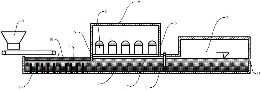
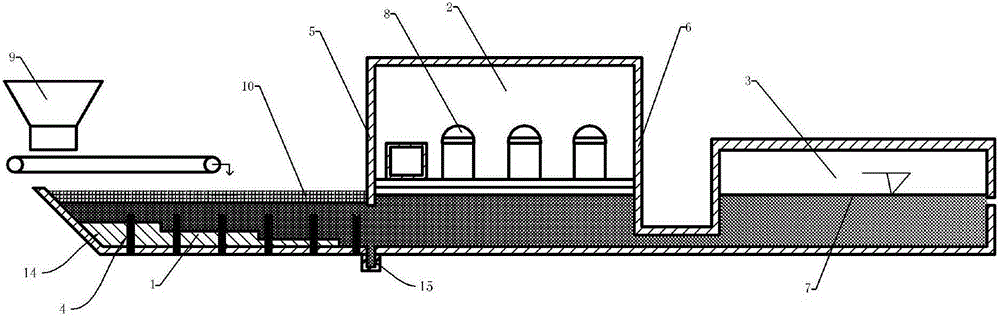
[0038] see figure 1 , a melting furnace for melting glass with high volatile components, including an electric melting pool 1, a flame refining pool 2 and a working part 3 distributed in sequence from left to right, the electric melting pool 1, flame refining pool 2. The molten glass in the working part 3 is connected, and the bot...


PUM


Abstract

The invention discloses a melting furnace for founding high-volatility-component glass. The melting furnace comprises an electric melting tank, a flame clarifying tank and a working part, wherein the electric melting tank, the flame clarifying tank and the working part are distributed in sequence from left to right; the bottom of the electric melting furnace is provided with heating electrodes; at least one group of oppositely arrayed combustion spray guns are arranged on two side surfaces, where a first partitioning suspended wall and a second partitioning suspended wall are not located, above the liquid level of the flame clarifying tank; the combustion guns generate flame gas flows through combustion to sweep a glass liquid level; the first partitioning suspended wall separates the electric melting tank from the flame clarifying tank; the second partitioning suspended wall separates the flame clarifying tank from the working part; the first partitioning suspended wall at least stretches to a position which is not less than 50mm below the liquid surface; a partitioning structure is arranged at a joint between the second partitioning suspended wall and the working part; the partitioning structure stretches into the glass liquid level for not les than 250mm; the working part is provided with a material discharging port; the melting furnace also comprises a material distributing device loaded with a compound material; the material distributing device vertically adds the compound material to be above the liquid level of the electric melting furnace; a cold roof covered material pile is formed.

Description

technical field [0001] The invention relates to a glass melting furnace, in particular to a melting furnace for melting glass with high volatile components. Background technique [0002] The pollution situation in our country is very severe, and the emission of smoke in the glass industry has become one of the important causes of a series of atmospheric environmental problems in our country. At present, there are two main ways to reduce the emission of waste gas from the glass industry: [0003] 1. Reduce the generation of flue gas in the melting process by reducing and optimizing the process; [0004] 2. Reduce the smoke emission caused by the volatilization of raw materials, which is more meaningful for the preparation of glass containing volatile components. [0005] Most of the existing glass melting furnaces use heavy oil or natural gas, and use air to support combustion. Because of its high temperature and high concentration of thermal nitrogen oxide emissions, some ...

Claims


Application Information

Patent Timeline
IPC IPC(8): C03B5/02
CPCY02P40/57
Inventor 李志进
Owner 江苏华东耀皮玻璃有限公司
Why Eureka
Try Eureka