

Coke oven ascending pipe waste-heat utilization equipment
A waste heat and coke oven technology, which is applied in the field of coke oven riser waste heat utilization equipment, can solve the problems of affecting the flow performance of working fluid, insufficient circulation, and easy deformation of the inner cylinder under stress, so as to solve the problems of coking and corrosion, increase Efficiency of waste heat recovery and effect of reducing possibility of coking
- Summary
- Abstract
- Description
- Claims
- Application Information
AI Technical Summary
Problems solved by technology
Method used
Image

Examples
Embodiment 1
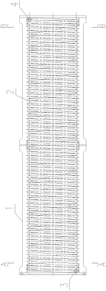
[0032] Such as Figure 1-3 As shown, this embodiment provides a coke oven riser waste heat utilization equipment, including a riser heat exchange device and a steam-water separator. The riser heat exchange device includes a shell, a heat insulation layer, a fire-resistant Layer and heat exchange channel 2;
[0033] Wherein, the heat exchange channel 2 includes a spirally arranged heat exchange pipe, two adjacent turns of the heat exchange pipe are closely attached to each other, and the outer wall of the heat exchange pipe facing the center of the heat exchange channel 2 is provided with a nano non-stick coating;
[0034] The heat exchange channel 2 includes a heat exchange pipe, and two adjacent turns of the heat exchange pipe are sealed and connected;
[0035] The shell is sealed and connected with the carbonization chamber and the bridge tube,
[0036] The upper end of the heat exchange pipe is provided with a steam-water mixture outlet 3, and the steam-water mixture outl...
Embodiment 2
[0046] On the basis of the above-mentioned embodiments, this embodiment provides a coke oven riser waste heat utilization device, which is different from Embodiment 1 in that: the heat exchange channel 2 includes two or more heat exchange pipes, Sealed connection between adjacent heat exchange pipes;
[0047] The upper ends of each of the heat exchange pipes are arranged at the same height, and the upper ends of each of the heat exchange pipes communicate with the upper communication pipe, and the upper communication pipe communicates with the steam-water mixture outlet 3,
[0048] The lower ends of the heat exchange pipes are arranged at the same height, and the lower ends of the heat exchange pipes communicate with the lower communication pipe, and the lower communication pipe communicates with the steam-water mixture outlet 3 .
[0049] In this embodiment, multiple heat exchange pipes are used, which can increase the amount of circulating water per unit time, so that the wa...
Embodiment 3
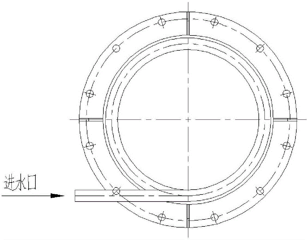
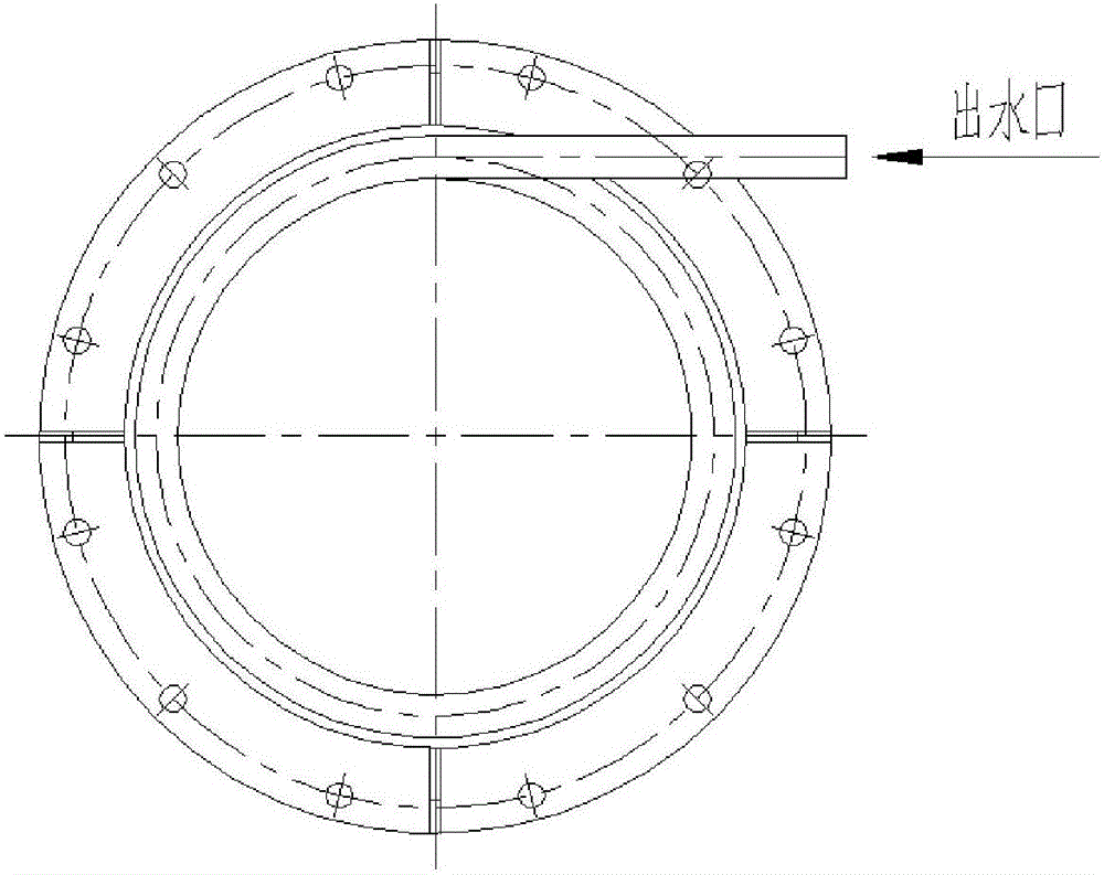
[0051] On the basis of the above embodiments, this embodiment provides a coke oven riser waste heat utilization equipment. In the riser waste heat equipment of this embodiment, connecting flanges are provided at both ends of the riser, and the connecting flanges It includes an annular horizontal connecting plate and a cylindrical vertical connecting plate, the inner diameter of the vertical connecting plate is equal to the outer diameter of the heat exchange channel 2, the horizontal connecting plate is connected with the housing 1, the The inner diameter of the horizontal connecting plate is equal to the inner diameter of the vertical connecting plate, and the horizontal connecting plate is coaxially connected with the vertical connecting plate.
[0052] The flange setting method of this embodiment can avoid the radial mutual movement of the heat exchange channel 2 and the shell 1, so as to ensure that the distance between the heat exchange channel 2 and the shell 1 is uniform...
PUM
 Abstract
Description
Claims
Application Information