
Ignition advancer and advance angle control optimization method of oil/CNG double-fuel engine

A dual-fuel engine, ignition advance angle technology, applied in the direction of automatic control, automatic control, electrical automatic control, etc., can solve the problems that cannot be adjusted, the angle is fixed, and cannot be adjusted, so as to improve reliability and eliminate error accumulation , Improve the effect of position accuracy

Inactive Publication Date: 2017-03-29
NORTH CHINA UNIV OF WATER RESOURCES & ELECTRIC POWER
View PDF8 Cites 6 Cited by
  • Summary
  • Abstract
  • Description
  • Claims
  • Application Information

AI Technical Summary

Problems solved by technology

At present, the oil / gas integrated controller is not yet mature, and the adjustment of the ignition advance angle is mainly realized through the additional ignition advancer. The existing ignition advancer has an advance angle of 6 o CA, 9 o CA, 12 o CA and 15 o CA, the adjustment of other angles cannot be realized, and the advanced angle is fixed within the range of the whole working condition, and cannot be adjusted according to the working condition

Method used


Image

  • Ignition advancer and advance angle control optimization method of oil/CNG double-fuel engine
  • Ignition advancer and advance angle control optimization method of oil/CNG double-fuel engine
  • Ignition advancer and advance angle control optimization method of oil/CNG double-fuel engine

Examples


Embodiment Construction

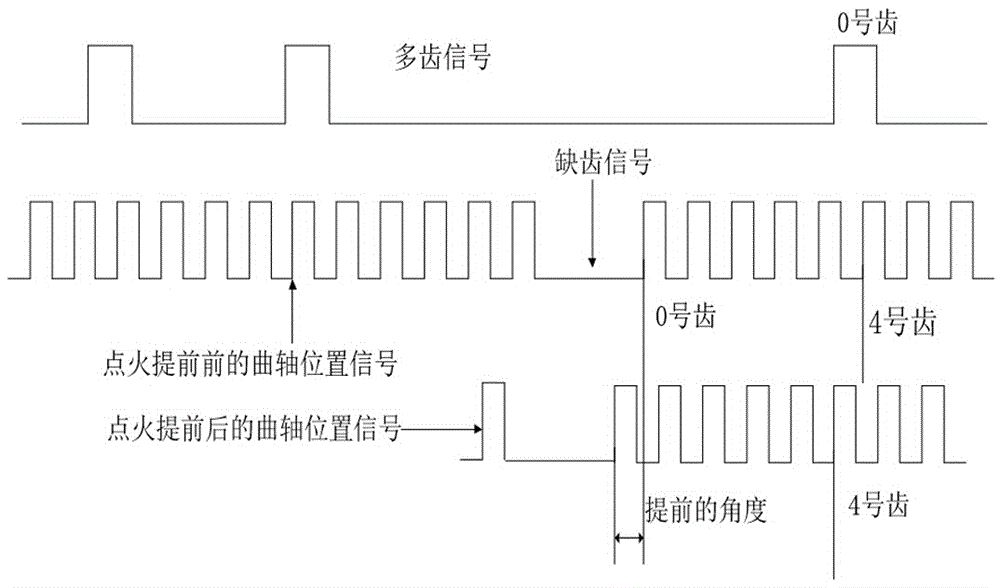
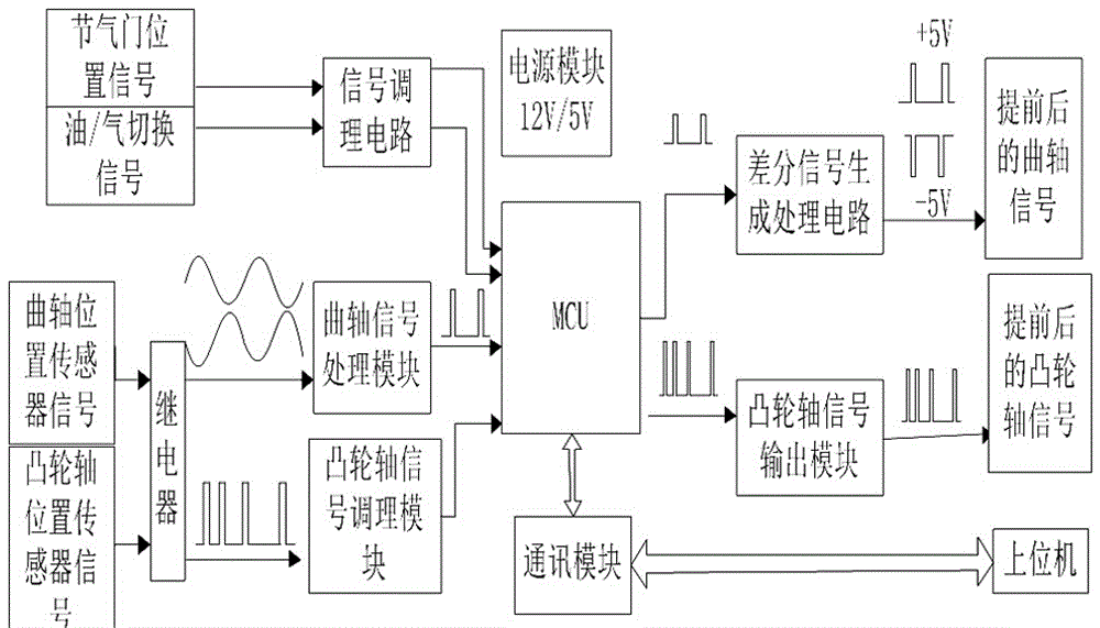
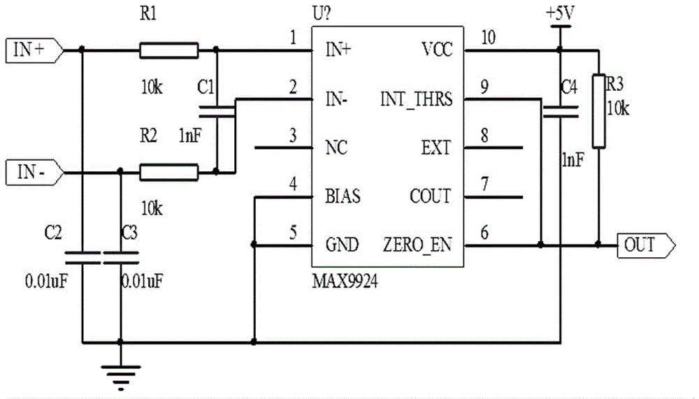
[0032] Attached below figure 1 ~9 and the specific implementation manner further describe the present invention in detail.

[0033] In the prior art, the engine crankshaft position sensor is generally a magnetoelectric sensor, which outputs two sine wave differential signals with different levels and frequencies according to the engine speed; the camshaft position sensor is a Hall sensor, which outputs a 5V TTL signal . When the ECU of the original machine is working, the synchronization is realized according to the characteristic teeth of the camshaft position sensor input signal and the characteristic teeth of the crankshaft position sensor input signal. After synchronization, the ignition advance angle is calculated from the value queried by MAP according to the existing algorithm to trigger ignition at a certain position of the crankshaft signal.

[0034] When the ignition advancer is working, the two crankshaft position signals, throttle position signal, camshaft positi...


PUM


Abstract

The invention provides an ignition advancer of an oil / CNG double-fuel engine. The ignition advancer of the oil / CNG double-fuel engine comprises an MCU, a differential signal generating and processing circuit, a power supply module and a communication module, wherein the differential signal generating and processing circuit is used for changing a crankshaft position signal transmitted by the MCU into a differential signal output circuit, and the communication module is used for communication between the ignition advancer and an upper computer. The invention further provides an ignition advance angle control optimization method of the oil / CNG double-fuel engine. The ignition advance angle control optimization method of the oil / CNG double-fuel engine comprises the following steps that (STP1), after the crankshaft position signal is acquired by the MCU, missing teeth of a bent shaft are captured; (STP2), the tooth number of one circle of the crankshaft is calculated according to the missing teeth of the crankshaft, and meanwhile, the degrees of rotating angles between the adjacent teeth are calculated; (STP3), through MAP calculation, an ignition advance angle required under the current working condition is calculated; and (STP4), according to the rotating angles, between the adjacent teeth, of the crankshaft and the required advance angle value, the position of analogue output of the next tooth is calculated. According to the ignition advancer of the oil / CNG double-fuel engine, adjusting of the ignition advance angle can be achieved under the full working conditions, and the types of the crankshaft signal and the camshaft signal can be automatically recognized through a system.

Description

technical field [0001] The invention relates to an ignition advancer for an oil-CNG dual-fuel engine and an optimization method for controlling the ignition advance angle. Background technique [0002] With the deterioration of the environment and increasingly stringent emission regulations, natural gas has become a good alternative fuel for vehicles due to its abundant reserves, low emission pollution, and good economy. At present, natural gas is mainly in the form of compressed natural gas (CNG) in vehicles to realize the work of oil / gas dual-purpose fuel mode. Add a set of gas supply system and control system (gas ECU) to the original car. The gas ECU obtains parameters such as the fuel injection pulse width and speed of the original car, and reads and adjusts the long-term fuel trim (long fuel trim) and short-term combustion according to the original car ECU at the same time. The short fuel trim value determines the gas injection pulse width. At the same time, the igni...

Claims


Application Information

Patent Timeline
Patent Type & Authority Applications(China)
IPC IPC(8): F02P5/15
CPCF02P5/15
Inventor 郭树满李权才王明吴金妹刘海潮纪占玲秦朝举刘焕
Owner NORTH CHINA UNIV OF WATER RESOURCES & ELECTRIC POWER
Learn More