
Apparatus for detecting component and detection method of apparatus for detecting component

A component and detection unit technology, which is applied to the equipment used to detect components and its detection field, can solve the problems of inability to meet the requirements of high-precision component detection and flexible production, flexible ability, and few detection items. Achieve the effects of shortening working hours, improving flexibility and compact structure

Active Publication Date: 2017-03-29
NINGBO SUNNY INTELLIGENT TECH CO LTD
View PDF12 Cites 13 Cited by
  • Summary
  • Abstract
  • Description
  • Claims
  • Application Information

AI Technical Summary

Problems solved by technology

However, although the detection capability of the vision system is getting stronger and stronger, the current vision detection equipment is still based on simple and single functions.
As described in CN104655649A, the single lens configuration determines that the whole set of equipment can only detect one or several specific products in a simple outline dimension detection in one direction, not only has fewer detection items, but also has more flexible capabilities. impossible to talk about
And described in CN105784719A " the machine visual inspection terminal machine that can carry out item classification ", although has added sorting function, but visual detection system still can only be analyzed to simple outline, thereby judges qualified or unqualified
[0008] In general, although visual inspection has developed from the early profiling analogy to today's computer calculation of specific element values, the existing visual inspection systems and equipment still only perform simple inspections on a single line of sight and limited types of inspection items. Unable to cope with high-precision, complex component testing requirements and flexible production needs

Method used


Image

  • Apparatus for detecting component and detection method of apparatus for detecting component
  • Apparatus for detecting component and detection method of apparatus for detecting component
  • Apparatus for detecting component and detection method of apparatus for detecting component

Examples


Embodiment approach

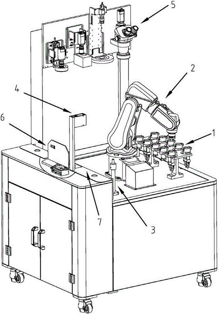
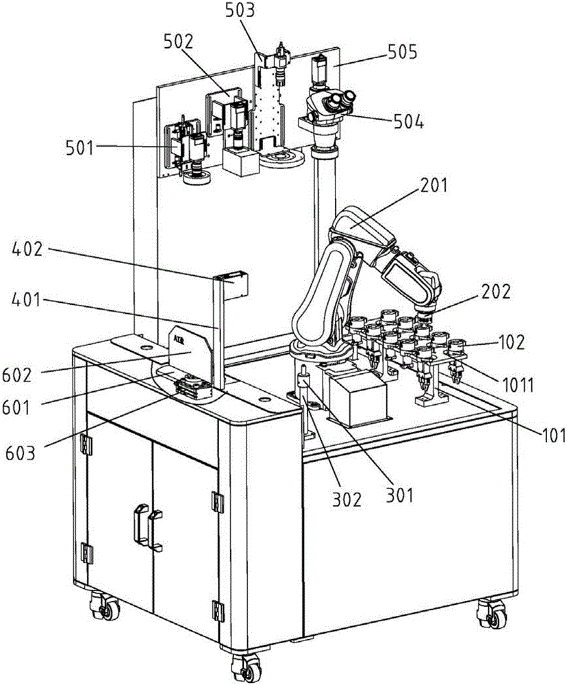
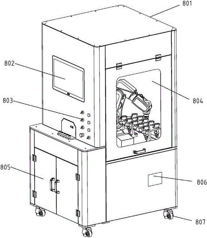
[0085] According to an embodiment of the present invention, the manipulator 201 first selects the end surface tooling 1023 when inspecting the components 901 . The manipulator 201 transports the component 901 from the detection station to the bottom of the first camera lens 501 in the detection unit 5 through the end surface tooling 1023, and the first camera lens 501 collects the components 901 such as inner diameter, slot width, slot center angle, etc. The computer system 802 of the equipment performs calculation and analysis to determine the detection information. After the inspection is completed, the manipulator 201 transports the components 901 to the transfer table 301 for temporary storage, and the manipulator 201 replaces the inner diameter tooling 1022 . The manipulator 201 transports the component 901 from the transfer table 301 to the bottom of the first camera lens 501 through the inner diameter tooling 1022, and collects the data of detection elements such as thi...


PUM


Abstract

The present invention relates to an apparatus for detecting a component. The apparatus for detecting the component comprises a fixture unit, an execution unit and a transit unit. The apparatus further comprises a depth detection unit used for collecting the surface hollow information of the component, and a detection unit used for collecting the size, shape and quality information of the component; and according to the detection unit, different kinds of camera lenses can be utilized to carry detection information visual recognition and collection on a tested workpiece according to different features and requirements. With the apparatus adopted, all-round and no-dead angle detection can be performed on the component; the high-precision camera lenses and a computing system are used in combination, so that accuracy and efficiency can be ensured.

Description

technical field [0001] The invention relates to a device for detecting external dimensions, surface shapes, internal processing quality, etc. of components and a method for detecting components. Background technique [0002] Chinese patent 201620009220.5 discloses an integral visual inspection platform. The device belongs to the field of assembly and inspection of automobile components. The device is directly connected with the robot device and the industrial camera, and uses the robot device to drive the movement of the industrial camera to detect the auto parts. During the inspection process, if an abnormality is found, the industrial camera will immediately take a photo to identify it, so as to find out the unqualified parts. This device is only suitable for the detection of some parts in automobiles, and has certain limitations. And because the auto parts do not move, the moving industrial camera detects the immobile auto parts, which makes the detection effect not go...

Claims


Application Information

Patent Timeline
Patent Type & Authority Applications(China)
IPC IPC(8): G01B11/00G01B11/22G01B11/24G01N21/88
CPCG01B11/00G01B11/22G01B11/24G01N21/88
Inventor 陈腾翁九星刘飞杨赛女赵姝炜
Owner NINGBO SUNNY INTELLIGENT TECH CO LTD
Learn More