Electric axle driving system and automobile

A drive system, electric vehicle technology, applied to vehicle components, control devices, transportation and packaging, etc., can solve the problems of compression and deceleration mechanism available space, volume increase, electric drive system volume increase, etc., to achieve the goal of increasing the transmission ratio Effect

Inactive Publication Date: 2017-04-05
SCHAEFFLER TECH AG & CO KG
View PDF6 Cites 2 Cited by
  • Summary
  • Abstract
  • Description
  • Claims
  • Application Information

AI Technical Summary

Problems solved by technology

Such a structure determines that if a sufficiently large transmission speed ratio is to be obtained, the volume of the spur gear pair needs to be large enough, because the transmission ratio of the spur gear pair depends on the ratio of the number of teeth of the two gears, so the large-volume reduction mechanism will lead to Increased volume of the overall electric drive system
Generally speaking, limited by the space layout and center distance requirements in ordinary electric vehicles, the speed ratio that can be realized is difficult to exceed 13, which also determines that the electric motor as the power source must have a large enough output power to meet the needs. , and the high-power motor not only has high cost, but also increases its volume accordingly. For the limited space in the car, it will further compress the available space of the deceleration mechanism, forming a vicious circle

Method used


Image

  • Electric axle driving system and automobile
  • Electric axle driving system and automobile

Examples


Embodiment Construction

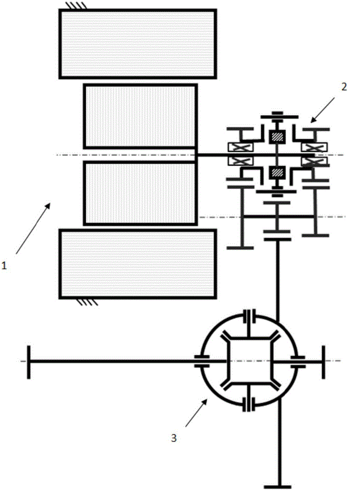
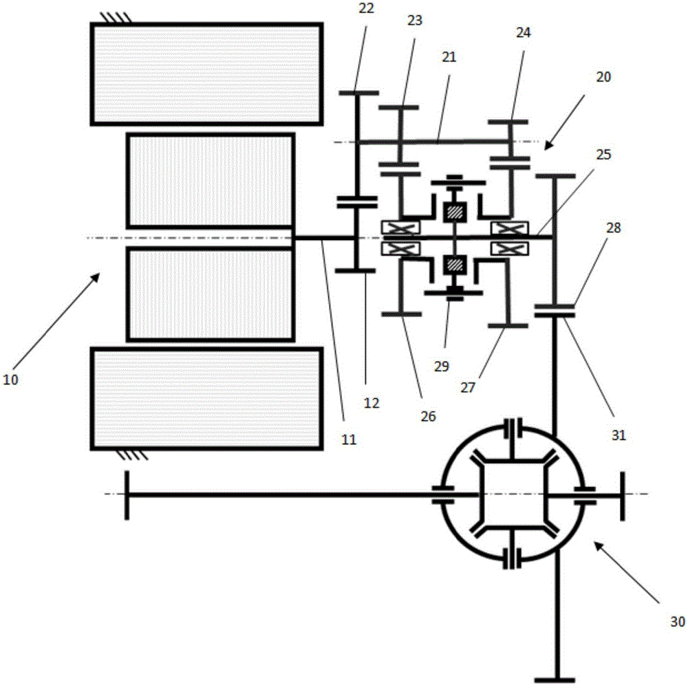
[0014] Such as figure 2 As shown, the electric shaft drive system of the first embodiment of the present invention includes a motor 10 , a reduction mechanism 20 and a differential 30 . Wherein the motor 10 has a stator located radially outside and a rotor located radially inside the stator, the rotor is fixedly connected with a motor output shaft 11 , and the motor output shaft 11 has a first fixed meshing gear 12 connected against torsion.

[0015] The reduction mechanism 20 includes an input shaft 21 and an output shaft 25 arranged in parallel. The second fixed meshing gear 22, the first II-speed gear 23 and the first I-speed gear 24 are arranged on the input shaft 21 in order to prevent rotation, and the second fixed meshing gear 22 is meshed with the first fixed meshing gear 12 on the output shaft of the motor to form a fixed meshing gear set to receive the power output from the output shaft 11 of the motor. The second II gear 26, the second I gear 27, and the first red...


PUM


Abstract

An electric axle driving system is used for an electric automobile or a hybrid electric vehicle and comprises a motor, a speed reduction mechanism and a differential mechanism. The speed reduction mechanism is used for amplifying driving force generated by the motor and allocating the driving force to wheels through the differential mechanism. The speed reduction mechanism can amplify the driving force through two different transmission ratios. In the process from driving force generation to allocation of the driving force to the wheels, amplification is conducted at least three times. Within the limited space range, the transmission ratio is increased, and accordingly the workpiece selection requirement of the motor is lowered or the torque output upper limit is increased.

Description

technical field [0001] The invention relates to an electric shaft drive system, in particular to an electric shaft drive system with a high-speed ratio, and an automobile with the electric shaft drive system. Background technique [0002] The electric drive mode of electric vehicles can basically be divided into two types: central motor drive and hub motor drive. A central motor drive system consisting of an electric motor, a fixed-ratio reducer, and a differential. In this drive system, since there is no clutch and transmission, the volume and mass of the mechanical transmission can be reduced. The central motor drive system can also have another layout, which is similar to the layout of a front-wheel drive, transverse front-engine fuel car, integrating the electric motor, fixed speed ratio reducer and differential, and two half shafts Connecting two drive wheels, this arrangement is called an electric axle drive system (eAxle drive system), and this arrangement is most c...

Claims


Application Information

Patent Timeline
Patent Type & Authority Applications(China)
IPC IPC(8): B60K17/08
Inventor 章俊杰俞正才
Owner SCHAEFFLER TECH AG & CO KG
Why Eureka
Try Eureka