Pump drive type two-phase fluid heat transport system

A heat transfer and fluid technology, applied in the direction of indirect heat exchangers, lighting and heating equipment, etc., can solve the problems of insufficient driving force, small cooling capacity, large air duct pipeline size, etc., and achieve the elimination of relative height restrictions, installation Ease of maintenance and reduced pipe diameter

Active Publication Date: 2017-04-05
SHENGRONGYUAN (SUZHOU) TECH CO LTD
View PDF6 Cites 7 Cited by
  • Summary
  • Abstract
  • Description
  • Claims
  • Application Information

AI Technical Summary

Problems solved by technology

Multi-connected air-conditioning system, such as patent number: a distributed cooling system for mobile communication base station equipment disclosed in CN101487640A, which has multiple evaporators to dissipate heat for the equipment respectively, and each evaporator needs a set of valves to implement throttling and control The flow rate, the system is complex, the reliability is insufficient, and the size of the air duct is large, and the consumables take up space; the single-phase cooling system such as the water cooling system uses the sensible heat of the working fluid to transfer heat, and the heat transfer efficiency is very low; the separated gravity heat pipe system, The heat exchange efficiency is high, but it only relies on gravity to drive the circulation of the working fluid and control the distribution of the working fluid between different evaporation branches, so there are insufficient driving force, limited location of cold and heat sources, and poor distribution of cold energy among multiple heat sources. Reasonable, the evaporator can not bear the high heat flux density and other problems; the liquid pump drives the multiple circuit heat pipe system, such as the patent number: CN102607120A discloses a liquid pump driven heat pipe device and operation method for cascade mechanical refrigeration, the device has sufficient driving force, The cooling capacity is large, and the location of cold and heat sources is not limited, but it does not solve the problem of cooling distribution among multiple heat sources
[0005] Not only is there an urgent need for heat dissipation in the communications industry, but at present most of the high-power electronic equipment on Chinese ships uses a water-cooled heat dissipation system. The cooling capacity of this cooling method is small, which limits the transmission power and continuous working time of the equipment. , the problem becomes more and more obvious

Method used


Image

  • Pump drive type two-phase fluid heat transport system
  • Pump drive type two-phase fluid heat transport system
  • Pump drive type two-phase fluid heat transport system

Examples


Embodiment Construction

[0044] Embodiments of the present invention will be described in detail below in conjunction with the accompanying drawings. This embodiment is carried out on the premise of the technical solution of the present invention, and the detailed implementation and specific operation process are given, but the protection scope of the present invention is not limited to the following embodiments.

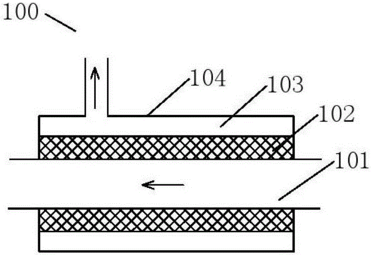
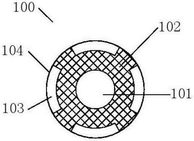
[0045] Single evaporator embodiment: figure 1 It is a longitudinal sectional view of a single evaporator embodiment in the present invention, figure 2 It is a cross-sectional view of a single evaporator embodiment of the present invention. Such as figure 1 and figure 2 As shown, the evaporator 100 includes a liquid channel 101 , a capillary wick 102 , a gas channel 103 and a housing 104 . The capillary wick 102 isolates the liquid channel 101 and the gas channel 103 of the evaporator 100 from each other. The capillary core 102 is a porous sintered structure, and its pore size can be an...


PUM


Abstract

The invention discloses a pump drive type two-phase fluid heat transport system. The system is provided with a fluid loop composed of a liquid pump, a primary liquid supply channel, at least one evaporation branch, a liquid gathering pipe, a gas gathering pipe, a gas-liquid mixer, a primary steam return channel, a condenser set, a liquid reservoir and a primary liquid return channel. The system is characterized in that each evaporation branch comprises a liquid supply branch, a liquid return branch, an evaporator and a gas branch; and each evaporator can be a single evaporator or a combined evaporator, a fluid channel composed of a liquid channel, a capillary core and a gas channel is formed in each single evaporator or each combined evaporator, and each capillary core isolates the corresponding liquid channel from the corresponding gas channel. According to the system, large cooling energy can be transported on the conditions of a small temperature difference and a long distance, after working media are vaporized in the evaporators, the gaseous working media and the liquid working media can be separated and can be transported through independent pipelines, and therefore the cooling energy can be automatically distributed for heat sources according to needs. The system is simple, reliable in operation and high in heat exchange efficiency.

Description

technical field [0001] The invention relates to the technical field of heat transfer equipment, in particular to a pump-driven two-phase fluid heat transfer system. Background technique [0002] As the power density and heating density of IT equipment in Internet data centers continue to increase, a series of insurmountable problems have emerged in traditional cooling methods in terms of cooling capacity distribution, heat dissipation efficiency, and noise. In recent years, the distributed cooling system, that is, the system that directly cools the heating equipment without cooling the entire equipment room, has been developed and applied. [0003] In addition to the heat dissipation requirements of the data center, the energy-saving requirements of the communication base station cooling system are also very urgent. The scale of my country's mobile communication network has ranked first in the world and is still expanding rapidly. At present, the industry consumes more tha...

Claims


Application Information

Patent Timeline
IPC IPC(8): F28D15/04
Inventor 赵秀红
Owner SHENGRONGYUAN (SUZHOU) TECH CO LTD
Why Eureka
Try Eureka