
Water cutting machine tool and filtering method

A cutting machine tool and water cutting technology, which is applied in the direction of filtration circuit, filtration separation, filtration treatment, etc., can solve the problems of reducing the service life of the filtration device, increasing the cost of parts and components, and reducing the effective working time, so as to improve the service life and realize Effect of recycling and optimizing cost control

Active Publication Date: 2017-04-19
JIAXING JINXILAI TECH CO LTD
View PDF5 Cites 1 Cited by
  • Summary
  • Abstract
  • Description
  • Claims
  • Application Information

AI Technical Summary

Problems solved by technology

[0003] At present, there are two treatment methods for the discharge water of water cutting machine tools. One is to directly discharge it without recycling it, resulting in waste of water resources; the other is to filter the discharge water through a filter device, so as to achieve recycling, but this method needs to stop the operation of the water cutting machine tool when replacing the filter device, which reduces the effective working time and increases the production cost
In addition, although the discharged water flowing into the water storage tank after being filtered by the filter device has reached the standard for the working water of the water cutting machine tool, the water in the water storage tank still has a certain degree of turbidity. Particles will accumulate in the slow flow area of ​​the relevant parts of the waterjet machine tool, thereby affecting the service life of these parts and increasing the cost of parts
Moreover, most of the filter devices have the problem of short filter cycle, the reason is that these filter devices can only perform forward filtration, and cannot perform internal reverse flushing, thereby reducing the service life of the filter devices

Method used


Image

  • Water cutting machine tool and filtering method
  • Water cutting machine tool and filtering method
  • Water cutting machine tool and filtering method

Examples


Embodiment Construction

[0033] Embodiments of the technical solutions of the present invention will be described in detail below in conjunction with the accompanying drawings. The following examples are only used to illustrate the technical solution of the present invention more clearly, and therefore are only examples, and should not be used to limit the scope of protection of this patent. In addition, the terms "first", "second", etc. are used for descriptive purposes only, and should not be understood as indicating or implying relative importance or implicitly specifying the quantity of the indicated technical features.

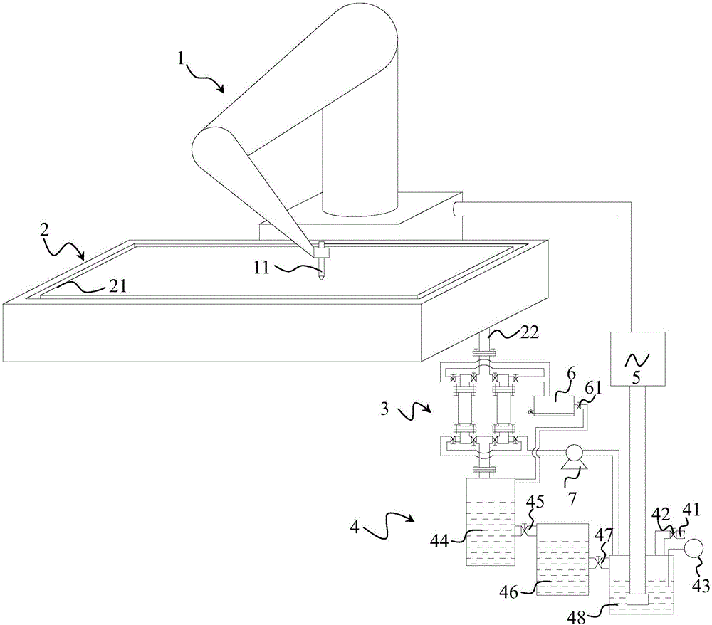
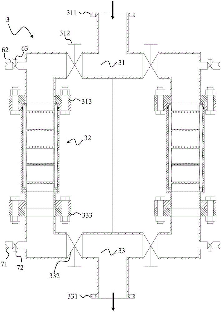
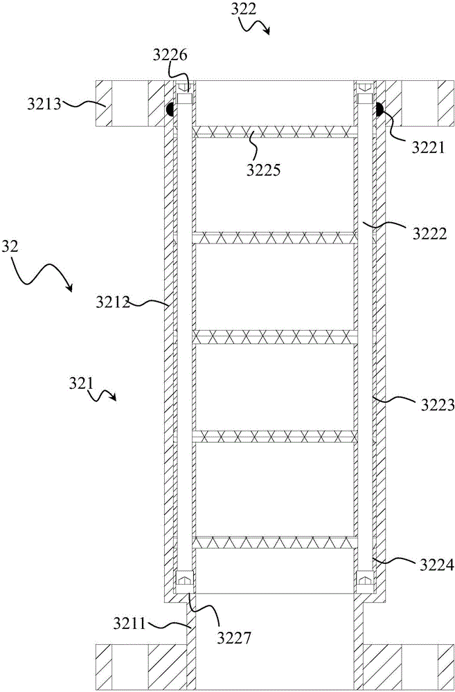
[0034] Such as figure 1 , figure 2 , image 3 , Figure 4 , Figure 5 with Image 6 As shown, this embodiment discloses a water cutting machine tool, including a mechanical arm 1, a cutting platform 2, a filter device 3, a water storage tank 4, a high-pressure pump 5 and a backwashing pool 6; the mechanical arm 1 is controlled by a control unit to cut The platform 2 is use...


PUM


Abstract

The present invention discloses a water cutting machine tool and a filtering method. The water cutting machine tool comprises a mechanical arm, a cutting platform, a filtering device, a water storage tank, a high-pressure pump and a backwashing pool; the filtering device is provided with two branch systems; when the filtering device is applied to online filtering, filtering portions can be replaced; the water storage tank is filtered level by level through a collection tank, a mitigation tank and a clear water tank; the high-pressure pump is used for generating high-pressure water which can be used by a nozzle on the mechanical arm; the mechanical arm is connected with a control unit; the nozzle on the mechanical arm operates on the cutting platform; the filtering device is arranged between the water outlet of the cutting platform and the water storage tank; the high-pressure pump is arranged between the water storage tank and the mechanical arm; the filtering device is connected with the backwashing pool; and a submerged pump is arranged between the filtering device and the clear water tank. With the water cutting machine tool and the filtering method adopted, on-line reverse cleaning of the filtering portions of the single branch systems can be realized, and the service lives of the filtering portions can be prolonged, and the use costs of the filtering portions can be decreased, and the cost control of the water cutting machine can be optimized.

Description

technical field [0001] The invention relates to the field of water cutting equipment, in particular to a water cutting machine tool and a filtering method. Background technique [0002] Water cutting is also called water jet cutting or water jet cutting, among which high-pressure water jet cutting is a special processing method, which uses a supercharger to pressurize water to a pressure of 10-400MPa or even higher, so that water can obtain pressure energy , and then ejected from a small nozzle, the pressure energy is converted into kinetic energy to form a high-speed jet, and the kinetic energy of this high-speed jet is used to impact and destroy the workpiece to achieve the purpose of cutting and forming. Water cutting will not produce harmful gas or liquid, and will not generate heat on the surface of the workpiece to cause work hardening. It belongs to the field of cold cutting processing and has the advantages of environmental protection, no pollution, high work efficie...

Claims


Application Information

Patent Timeline
IPC IPC(8): B23D79/00B01D36/04C02F9/02
CPCB01D36/04B23D79/00C02F1/001C02F1/52
Inventor 郭洪宇
Owner JIAXING JINXILAI TECH CO LTD
Learn More