Double-robot base coordinate system calibration method based on laser tracker

A laser tracker and dual-robot technology, applied to instruments, optical devices, measuring devices, etc., can solve the problems of the calibration results being affected by human errors, the tedious and time-consuming teaching process, and the tedious preparation work, etc., so as to avoid the calibration accuracy. Influence, improve the calibration efficiency, shorten the time effect

Inactive Publication Date: 2017-04-26
SOUTH CHINA UNIV OF TECH +1
View PDF5 Cites 35 Cited by
  • Summary
  • Abstract
  • Description
  • Claims
  • Application Information

AI Technical Summary

Problems solved by technology

Contact calibration has high requirements for the operator to teach, the calibration result is affected by human error, the teaching process is cumbersome and time-consuming, and the calibration efficiency is not high
Non-contact calibration uses external equipment such as laser tracker, CCD camera, electronic theodolite, etc

Method used


Image

  • Double-robot base coordinate system calibration method based on laser tracker
  • Double-robot base coordinate system calibration method based on laser tracker
  • Double-robot base coordinate system calibration method based on laser tracker

Examples


Embodiment 1

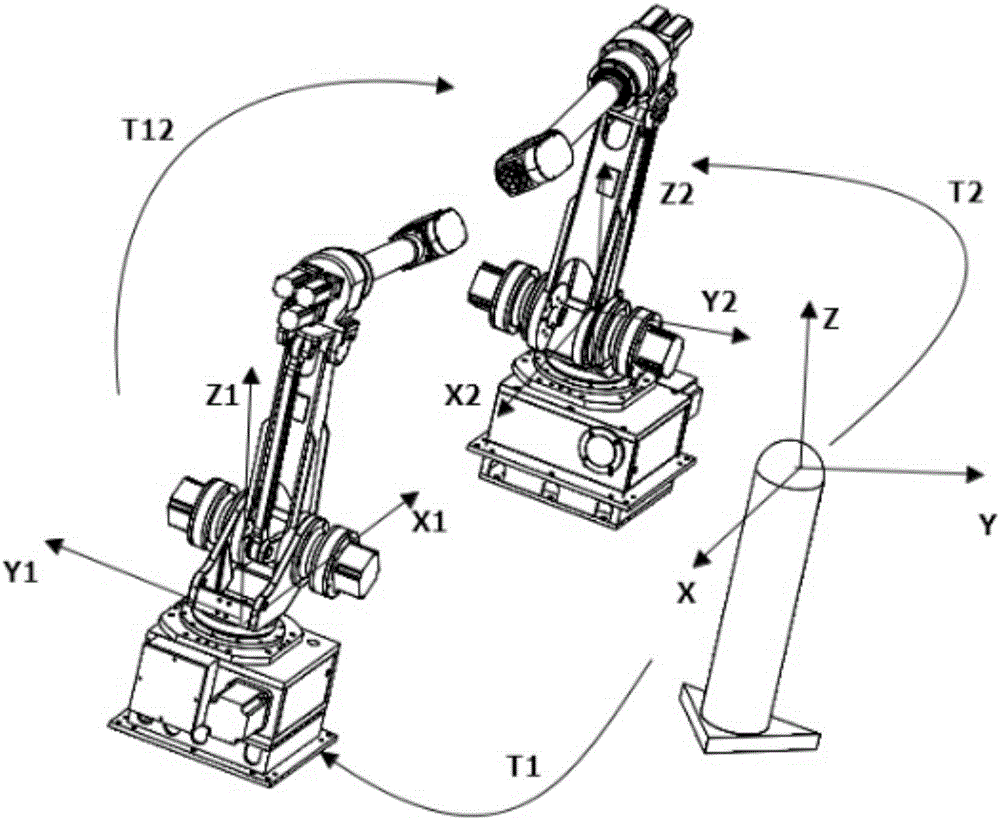
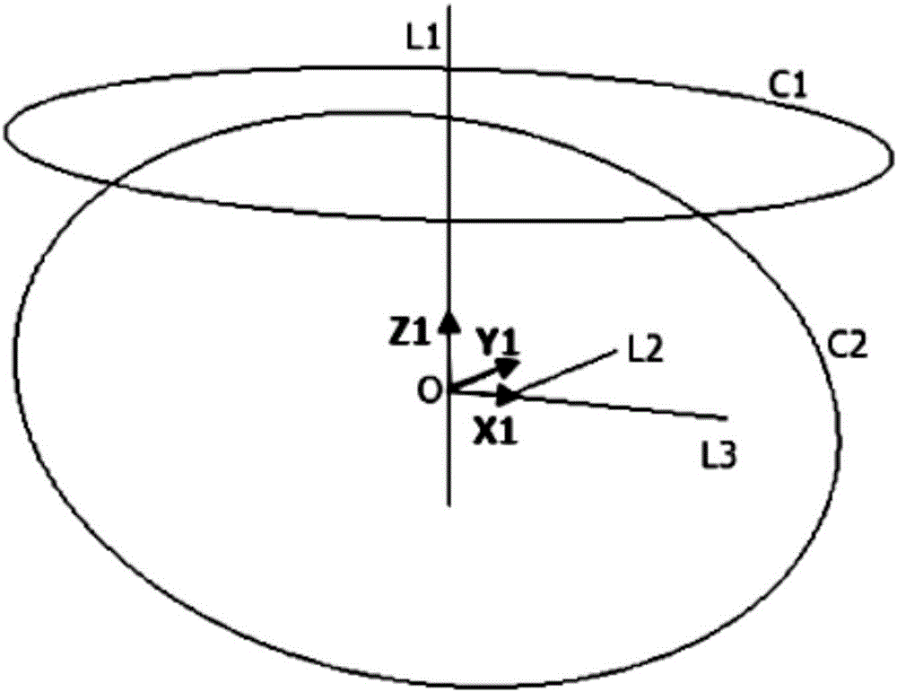
[0040] Such as figure 1 As shown, the laser tracker is set up near the dual robots, and the magnetic target ball seat is adsorbed on the end flange of the robot. The target ball of the laser tracker is placed on the target ball seat to ensure that the position of the target ball is fixed during the calibration process. Do not move.

[0041] Control the robot so that it is in the zero position. Control the first axis of the robot to perform single-axis rotation, and the other five axes do not rotate. Record the coordinates of the center of the target ball at certain angles, record n ​​points in total, and obtain the point group P1=(x P1i ,y P1i ,z P1i )(i=1,2...n), return the robot to the zero point after the rotation is completed.

[0042] Control the second axis of the robot to perform single-axis rotation, and the other five axes do not rotate. Record the coordinates of the center of the target ball at certain angles, record n ​​points in total, and obtain the point grou...

Embodiment 2

[0051] The laser tracker and supporting data processing software Spatial Analyzer are used to realize rapid calibration and greatly improve the calibration efficiency.

[0052] Such as figure 1 As shown, the laser tracker is set up near the dual robots, and the magnetic target ball seat is adsorbed on the end flange of the robot. The target ball of the laser tracker is placed on the target ball seat to ensure that the position of the target ball is fixed during the calibration process. Do not move.

[0053] Control the robot so that it is in the zero position. Control the first axis of the robot to perform single-axis rotation, and the other five axes do not rotate. Record the coordinates of the center of the target ball in the Spatial Analyzer at certain angles, record n ​​points in total, and obtain the point group P1=(x P1i ,y P1i ,z P1i )(i=1,2...n), return the robot to the zero point after the rotation is completed.

[0054] Control the second axis of the robot to pe...


PUM


Abstract

The invention discloses a double-robot base coordinate system calibration method based on a laser tracker. For two robots with the cooperation relation, the method employs a high-precision laser tracker measurement system to determine a homogeneous transformation matrix of each robot base coordinate system relative to a laser tracker coordinate system, and achieves the determining of the relative posture relation between the two robot base coordinate systems through a coordinate transformation method. The method is simple in operation, and the calibration process exerts low requirements on the operation of the robots. The calculation process of the calibration method does not refer to the readings of internal coders of the robots and joint angle values, thereby avoiding the calibration precision impacts from an operation error and a robot error. Meanwhile, the method employs the advantage that a laser tracker device is high in measurement precision, so the calibration result is high in precision. The method provided by the invention is simple in operation, remarkably shortens the time, and improves the calibration efficiency.

Description

technical field [0001] The invention relates to the field of advanced manufacturing of industrial robots such as robot collaborative handling, welding, and assembly, and specifically relates to a laser tracker-based calibration method for a dual-robot base coordinate system, especially for vertically articulated collaborative robots. Background technique [0002] Robots are important equipment in industrial automation production, and have been widely used in welding, handling, spraying and other fields. As the field of application expands, robots will perform more and more complex tasks. For tasks such as handling large objects, processing workpieces with complex trajectories, and tasks that require a large range of motion, a single industrial robot can no longer meet the production requirements well, and the coordination of two or more robots can solve the above problems. Therefore, Multi-robots, especially dual-robot collaborative systems will become the development trend...

Claims


Application Information

Patent Timeline
IPC IPC(8): G01B11/00
CPCG01B11/002
Inventor 王念峰张飞跃周建斌张宪民郑永忠周生勇
Owner SOUTH CHINA UNIV OF TECH
Why Eureka
Try Eureka