
OLED display device

A display device and cover plate technology, which is applied in the manufacturing of electrical components, electric solid-state devices, semiconductor/solid-state devices, etc., can solve the problems of poor sealing effect, sealing effect, insufficient heat dissipation efficiency, and shortened life of OLED devices of OLED display devices. Achieve good mechanical strength, eliminate static electricity, and improve quality.

Active Publication Date: 2017-04-26
TCL CHINA STAR OPTOELECTRONICS TECH CO LTD
View PDF5 Cites 17 Cited by
  • Summary
  • Abstract
  • Description
  • Claims
  • Application Information

AI Technical Summary

Problems solved by technology

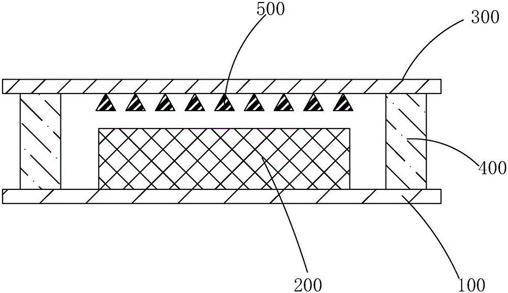
However, the OLED display device has a poor sealing effect and can only block external water vapor to a certain extent. Part of the water vapor will still invade the OLED device 200 through the sealant 400 and shorten its life. Low, heat accumulation will still be generated, which will directly shorten the life of the OLED device, and cause the water vapor in each film layer to be heated and discharged, which will aggravate the shortening of the life of the OLED device
South Korea's LG Company currently uses full-cathode bonding adhesive plus transparent or non-transparent metal cover to realize the packaging and bonding of OLED devices, which still has insufficient sealing effect and heat dissipation efficiency. At the same time, due to the use of metal cover, the cost of the product Increase

Method used


Image

  • OLED display device
  • OLED display device
  • OLED display device

Examples


Embodiment Construction

[0025] In order to further illustrate the technical means adopted by the present invention and its effects, the following describes in detail in conjunction with preferred embodiments of the present invention and accompanying drawings.

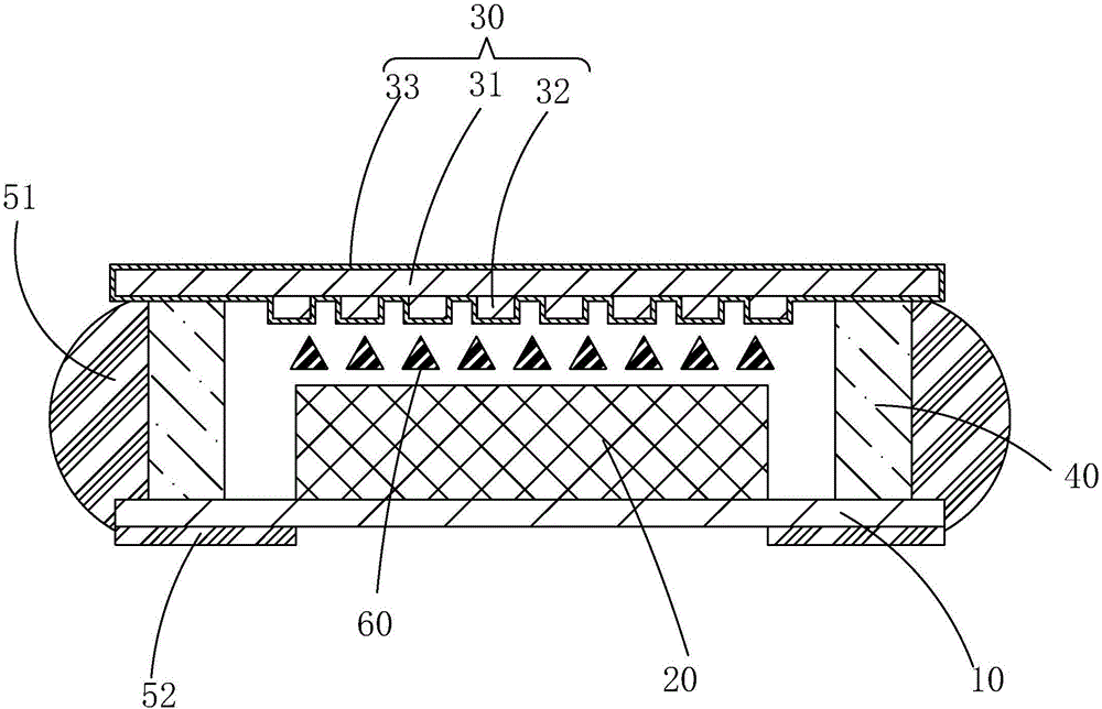
[0026] see figure 2 , the present invention provides an OLED display device, comprising a substrate 10, an OLED device 20 disposed on the substrate 10, a cover plate 30 disposed above the OLED device 20, and disposed between the cover plate 30 and the substrate 10. The sealant 40 located on the periphery of the OLED device 20, the first thermally conductive light-shielding layer 51 coated on the outside of the sealant 40, the area on the cover plate 30 other than the sealant 40, and the area on the substrate 10 other than the sealant 40, A second thermally conductive light-shielding layer 52 coated on the bottom of the substrate 10 corresponding to the area outside the OLED device 20 , and a desiccant 60 filled between the cover plate 30 and ...


PUM

PropertyMeasurementUnit
Thicknessaaaaaaaaaa
Thicknessaaaaaaaaaa

Abstract

The invention provides an OLED display device. A plurality of projections are arranged on one surface of a side, positioned close to an OLED device, of a cover plate substrate; outer surfaces of the cover plate substrate and the plurality of projections are wrapped with heat conduction layers, heat radiation area and heat radiation efficiency of a cover plate can be increased, service life of the OLED device can be prevented from being reduced due to heat accumulation, and the cover plate is enabled to be high in mechanical strength; a first heat conducting and light shielding layer including graphene and light shielding material is coated on an outer side of sealing gum, on an area, positioned outside the sealing gum, of the cover plate and on an area, positioned outside the sealing gum, of a base plate; a second first heat conducting and light shielding layer is coated on an area, positioned outside a part corresponding to the OLED device, of a bottom part of the base plate; the OLED display device can be prevented from all-around light leakage while air tightness of the OLED device can be enhanced, external moisture can be effectively prevented from permeating the OLED device, the service life of the OLED device can be prevented from being affected, heat radiation efficiency of the OLED display device can be further improved due to excellent thermal conductivity and electrical conductivity of the graphene material, the OLED display device can be free from static electricity, and product quality can be improved.

Description

technical field [0001] The invention relates to the field of display technology, in particular to an OLED display device. Background technique [0002] Organic light-emitting diode (Organic Light-Emitting Diode, OLED) display, also known as organic electroluminescent display, is a new type of flat panel display device, due to its simple preparation process, low cost, low power consumption, high luminance, Wide range of working temperature, light and thin size, fast response speed, easy to realize color display and large-screen display, easy to realize matching with integrated circuit driver, easy to realize flexible display, etc., so it has broad application prospects. [0003] OLED generally includes: a substrate, an anode disposed on the substrate, a hole injection layer (Hole Inject Layer, HIL) disposed on the anode, a hole transport layer (Hole Transport Layer, HTL) disposed on the hole injection layer, a device The light-emitting layer on the hole transport layer, the ...

Claims


Application Information

Patent Timeline
IPC IPC(8): H01L51/52H01L23/60
CPCH01L23/60H10K50/8426H10K50/87H10K50/865
Inventor 马超
Owner TCL CHINA STAR OPTOELECTRONICS TECH CO LTD
Learn More