Low-profile high-gain dual-polarized antenna

A dual-polarized antenna, high-gain technology, applied in the combination of antenna units with different polarization directions, the structural connection of the antenna grounding switch, the structural form of the radiating element, etc. The antenna is difficult to meet the needs of antenna miniaturization, destroying the excellent radiation characteristics of the patch antenna, etc., achieving significant performance advantages, facilitating mass production, and easy conformal design.

Inactive Publication Date: 2017-04-26
UNIV OF ELECTRONICS SCI & TECH OF CHINA
View PDF1 Cites 14 Cited by
  • Summary
  • Abstract
  • Description
  • Claims
  • Application Information

AI Technical Summary

Problems solved by technology

[0005] (1) Passive component loading often destroys the excellent radiation characteristics of the original patch antenna, resulting in a decrease in the overall performance of the antenna, such as radiation efficiency decline, pattern distortion, cross-polarization deterioration, etc.; at the same time, traditional passive component loading technology It will inevitably involve additional processing techniques such as vias, welding, and embedding, which makes the processing procedures very complicated, which is not conducive to large-scale production and processing.
[0006] (2) In order to ensure the performance of single-layer double-patch and double-layer double-patch, the lateral or cross-sectional size of the antenna is often increased, making the overall size of the antenna larger, so that it is difficult for this antenna to meet the needs of antenna miniaturization in today's society
Methods commonly used to increase antenna gain include using parasitic elements as directors, using larger metal backplanes, etc. These methods will greatly increase the volume and profile height of the antenna, which is very unfavorable for the miniaturization and thinning of the antenna application requirements

Method used


Image

  • Low-profile high-gain dual-polarized antenna
  • Low-profile high-gain dual-polarized antenna
  • Low-profile high-gain dual-polarized antenna

Examples


Embodiment

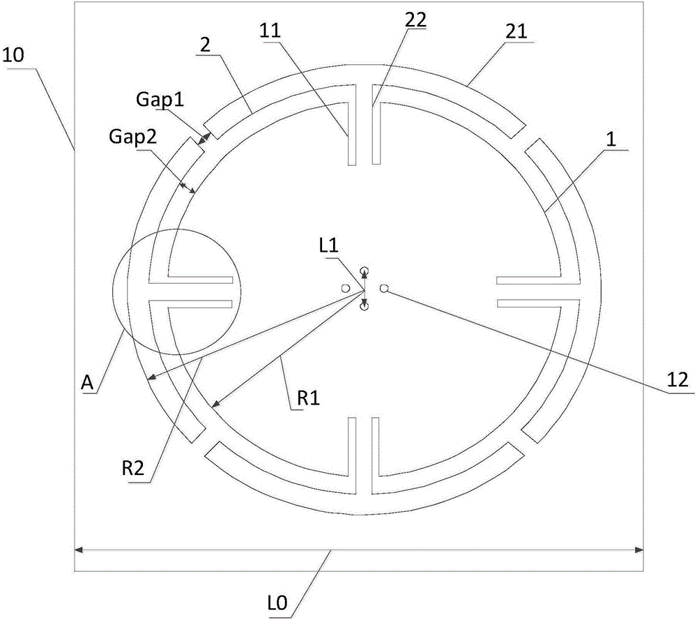
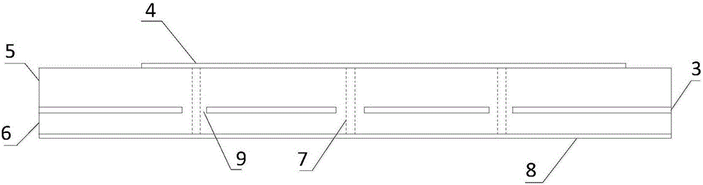
[0032] Such as Figure 1 to Figure 3 As shown, a low-profile high-gain dual-polarized antenna includes a feed network layer 8, a second dielectric substrate layer 6, a metal ground layer 3, a first dielectric substrate layer 5, and a radiation layer 4 stacked sequentially from bottom to top. , and four metal wires vertically passing through the feed network layer 8, the second dielectric substrate layer 6, the metal ground layer 3, the first dielectric substrate layer 5 and the radiation layer 4, and electrically connecting the radiation layer 4 and the feed network layer 8 Probe 7; when the metal probe 7 passes through the metal formation 3, four third openings 9 that are not electrically connected to the metal probe 7 are formed.

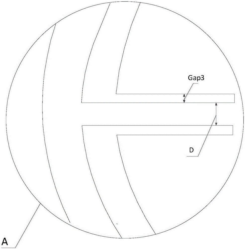
[0033] The radiation layer 4 includes a circular metal patch 1 and four "T"-shaped metal patches 2 that generate parasitic resonance; four metal probes 7 form four first openings 12 in the radiation layer 4 in a circular The center of the metal p...


PUM


Abstract

The invention discloses a low-profile high-gain dual-polarized antenna, and the antenna is characterized in that the antenna comprises a feed network layer, a second dielectric substrate layer, a metal ground layer, a first dielectric substrate layer and a radiation layer, wherein the feed network layer, the second dielectric substrate layer, the metal ground layer, the first dielectric substrate layer and the radiation layer are sequentially stacked; the antenna also comprises four metal probes which vertically pass through the feed network layer, the second dielectric substrate layer, the metal ground layer, the first dielectric substrate layer and the radiation layer, and are electrically connected with the radiation layer and the feed network layer; the radiation layer comprises a circular metal paster and four T-shaped metal pasters which generate parasitic resonance; four first openings formed by the four metal probes on the radiation layer takes the circle center of the circular metal paster as the center, thereby forming four corners of a first square. According to the invention, the antenna employs the T-shaped metal pasters as parasitic resonance structure units, thereby enabling the bandwidth of the antenna to be effectively enlarged. Moreover, the T-shaped structures and the circular paster are located in the same layer, so the machining is easy, and the large-scale production is facilitated.

Description

technical field [0001] The invention relates to the field of dual-polarization antennas, in particular to a low-profile high-gain dual-polarization antenna. Background technique [0002] The polarization of the antenna is one of the main parameters that affect the performance of the antenna, and it is also an important parameter that needs to be considered in designing the antenna. The polarization of the antenna refers to the direction of the electric field strength formed when the antenna radiates. According to the different polarization directions, the antenna can be divided into a single-polarized antenna and a dual-polarized antenna; usually, mutually orthogonal dual-polarized antennas work at the same time In the transceiver duplex mode, its most prominent advantage is to save the number of antennas of a single directional base station. [0003] The 2.4GHz frequency band is a common public basic frequency band all over the world. Various communication devices work in ...

Claims


Application Information

Patent Timeline
Patent Type & Authority Applications(China)
IPC IPC(8): H01Q1/38H01Q1/50H01Q21/24
CPCH01Q1/38H01Q1/50H01Q21/24
Inventor 黄发熊江邵维
Owner UNIV OF ELECTRONICS SCI & TECH OF CHINA
Why Eureka
Try Eureka