Back-cavity antenna for X-band probe feeding

An X-band and slot antenna technology, applied in the field of slot antennas, can solve the problems of antenna stability not reflected, phase center stability cannot be guaranteed, and working frequency band is narrow, and achieve good application prospects, simple structure, and stable gain.

Active Publication Date: 2017-04-26
XIAMEN UNIV
View PDF4 Cites 4 Cited by
  • Summary
  • Abstract
  • Description
  • Claims
  • Application Information

AI Technical Summary

Problems solved by technology

[0003] Chinese patent 201510083218.2 discloses a linearly polarized cavity-backed antenna, which has the advantage of low cross-polarization, but has a narrow operating frequency band
[0004] Chinese patent 201320611774.9 discloses a linear miniaturized tapered slotted antenna, which has a very wide frequency band, but if used as a feed unit of a lens system, the antenna has a large size and cannot guarantee the stability of the phase center
In addition, whether the gain of the antenna is stable within a certain bandwidth is not reflected

Method used


Image

  • Back-cavity antenna for X-band probe feeding
  • Back-cavity antenna for X-band probe feeding
  • Back-cavity antenna for X-band probe feeding

Examples


Embodiment Construction

[0020] The present invention will be further described in conjunction with accompanying drawing and specific embodiment now, please refer to Figure 1~3 .

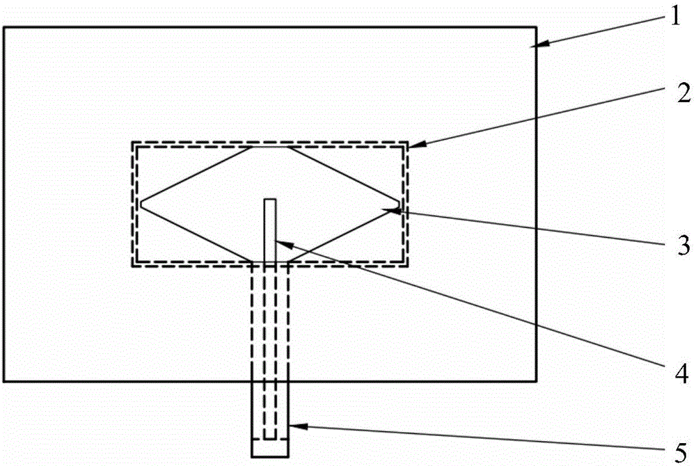
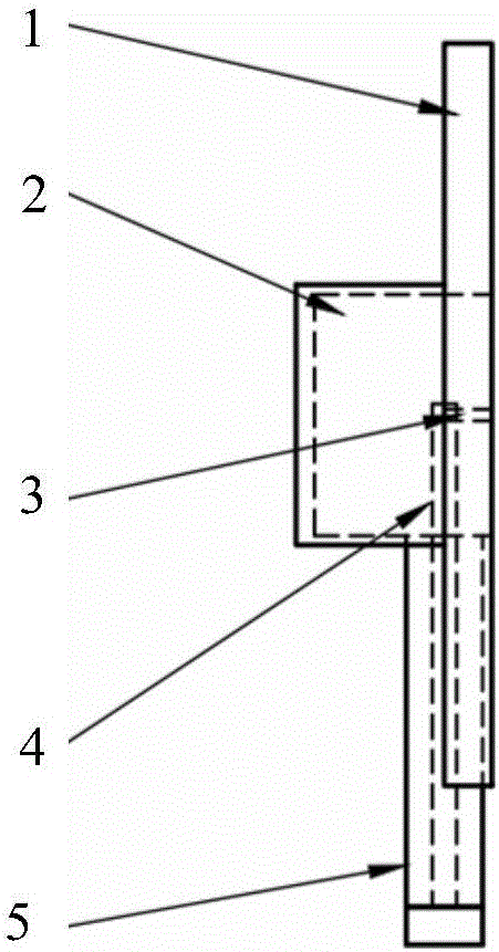
[0021] The main working principle of the present invention is: the back cavity 2 and the slot 3 work together to make the electromagnetic field radiate outward through the slot, and the back cavity 2 plays the role of binding the electromagnetic field and making the electromagnetic wave radiate in one direction. The size of the metal floor 1 can be determined according to specific application occasions, the smaller the size, the greater the effect of edge diffraction on the radiation performance of the antenna. The interior of the back cavity 2 is filled with air instead of a medium with a certain dielectric constant, which can reduce the loss of the antenna, thereby reducing the impact on the gain.

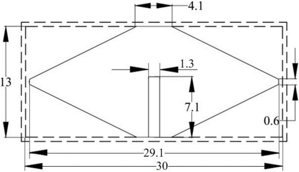
[0022] The inner diameter of the feeding coaxial line 4 is 1.3 mm, and the outer diameter is 4.1 mm. The feeding probe 5 e...


PUM


Abstract

The invention discloses a back-cavity antenna for X-band probe feeding in relation to a cavity antenna and provides a back-cavity antenna for X-band probe testing featuring one direction radiation, wide frequency band, stable gain and stable phase center. The antenna of the invention comprises a metal grounding plate, a back cavity, a feeding coaxial line and a feeding probe. The back cavity is arranged at one side of the metal grounding plate; the metal grounding plate is provided with a slot; the back cavity and the slot are used for an electromagnetic field to realize externally one direction radiation through the slot; the feeding coaxial line feeds towards the slot through the feeding probe. The antenna of the invention is simple in structure and small in size. The antenna also has a wide frequency band and stable gain and can be used as a single antenna or combined with lenses for use. The antenna of the invention can be widely applied in the following fields of space research, broadcasting satellites, fixed communication business satellites, global detection satellites and meteorological satellites.

Description

technical field [0001] The invention relates to a slot antenna, in particular to a cavity-backed slot antenna fed by an X-band probe. Background technique [0002] Slot antenna has become a very active field of antenna research in recent years due to its simple structure and easy processing. For example, Chinese Patent No. 201110052089.2 discloses a slotted antenna, which can adjust the radiation field by switching the switch and enhance the ability of transmitting and receiving signals, so that it can be well applied to wireless communication devices. However, many conventional slot antennas currently have bandwidth limitations and cannot achieve better radiation characteristics in a wide frequency band. The so-called cavity-backed slot antenna is to open a gap on the wall of a closed cavity. The electromagnetic energy is radiated from the gap. It has the advantages of simple structure, small size, small radiation loss, wide bandwidth and stable gain. It can be used as a b...

Claims


Application Information

Patent Timeline
Patent Type & Authority Applications(China)
IPC IPC(8): H01Q13/20H01Q1/50
CPCH01Q1/50H01Q13/20
Inventor 刘颜回白晶晶姚志会徐开达邓丽丽
Owner XIAMEN UNIV
Why Eureka
Try Eureka