Three-degrees-of-freedom MEMS piston-tube electrostatic microactuator

A micro-actuator and actuator technology, applied in the direction of electrostatic motors, piezoelectric devices/electrostrictive devices, piezoelectric/electrostrictive/magnetostrictive devices, etc., can solve the limitations of VCD actuators, rotor Misalignment of electrode and stator electrode joints, micromachining process is not capable of realizing, etc., to achieve the effect of doubling the stroke

Active Publication Date: 2017-04-26
SHEBA MICROSYST INC
View PDF14 Cites 20 Cited by
  • Summary
  • Abstract
  • Description
  • Claims
  • Application Information

AI Technical Summary

Problems solved by technology

[0014] (2) If the bulk micromachining fabrication process (bulk micromachining fabrication process) is used to fabricate a translational VCD actuator with a cavity tooth configuration, there may be misalignment of the joint between the rotor electrodes and the stator electrodes
[0016] (4) Surface micromachined VCD actuators are limited in being able to provide large translational (piston) strokes
This limitation is due to the inability of the surface micromachining processes used to deposit layers of large height (thickness) to achieve

Method used


Image

  • Three-degrees-of-freedom MEMS piston-tube electrostatic microactuator
  • Three-degrees-of-freedom MEMS piston-tube electrostatic microactuator
  • Three-degrees-of-freedom MEMS piston-tube electrostatic microactuator

Examples


Embodiment approach 1

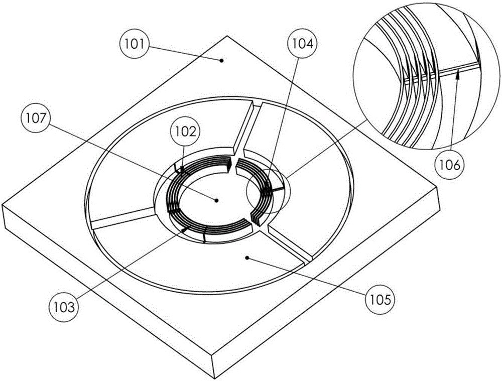
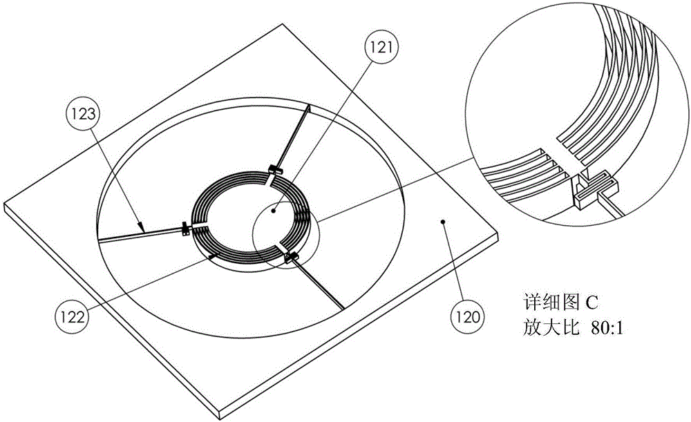
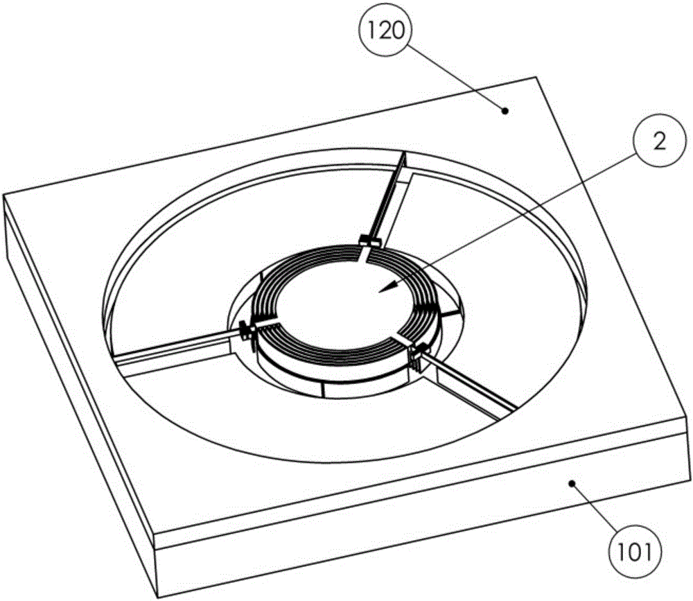
[0050] A first embodiment of the invention (3-DOF MEMS electrostatic actuator) is shown in FIG. 1 . like Figure 1A As shown, the fixed structure in this embodiment comprises a plurality of concentric arc-shaped teeth (pistons) 102, 103, 104, and the moving structure comprises a plurality of concentric teeth sized and designed to receive the teeth of the fixed structure. Arc-shaped groove or opening (pipe) 122 ( Figure 1B ).

[0051] The teeth or pistons are divided into three stators 102, 103, 104 arranged at 120°. Each stator includes a plurality of arcuate pistons that are vertically aligned with arcuate tubes (openings) 122 in the rotor such that they intersect each other during actuation. The three stators 102, 103, 104 are electrically isolated from each other by a buried oxide (BOX) layer 107 using an SOI wafer. However, the electrodes of each stator are electrically connected via a layer of small thickness (height) 106 above the BOX layer. The three circular islan...

Embodiment approach 2

[0057] In order to avoid the limitations of Embodiment 1 in terms of biaxial rotation, the poles of the stator and rotor may be arranged in a manner that reduces the variation of the gap 126 during rotation. exist Figure 2A The pistons 204, 205, 206, 207 in this embodiment shown in , extend radially from the interior of the actuator to the exterior periphery. A parallel plate capacitor between the piston and the side of the tube extends in the radial direction of the circular plate of the actuator. Therefore, during rotation of the actuator, negligible variation in horizontal gap (g) 126 is expected for those charged piston-tube pairs that are perpendicular or nearly perpendicular to the axis of rotation. These charged piston tube pairs also produce a nearly linear relationship of torque to voltage. This is especially true when the stator layer is divided into a large number of stators, see Figure 2D (Although the figure shows a 4 stator actuator, the stator layer can be ...

Embodiment approach 3

[0059] Another embodiment of the actuator is shown in FIG. 3 . In this embodiment the pistons 304, 305, 306, 307 have a rectangular cross-section and they protrude vertically towards the rotor and extend horizontally along two in-plane axes (x and y). Each opposing stator contains a plurality of rectangular pistons also extending horizontally along two in-plane axes (x and y). The tubes 310 in the rotor are rectangular through holes and they face the pistons so that the pistons penetrate along the tubes during actuation. Compared to Embodiment 2 where the corners of the actuator are not utilized due to the circular rotor geometry, this design is more area efficient in terms of total electrode capacitance. It also utilizes an efficient spring configuration similar to that used in Embodiment 2. However, due to the change in horizontal clearance between adjacent pistons and tubes, the angle of rotation of this embodiment is limited, especially when the actuator plate is rotated...


PUM


Abstract

A three-degrees-of-freedom MEMS electrostatic piston-tube actuator is disclosed. The actuator comprises two structures. A structure that comprises a plurality of fixed piston-like electrodes that are attached to a base, and form the stator of the actuator. A second structure that comprises a plurality of moving tube-like electrodes that are attached to the body of the upper structure and form the rotor of the actuator. The rotor is attached to the stator through a mechanical spring. The rotor of the actuator provides a 3-DOF motion, comprising vertical translation and bi-axial rotation about the axes of the structures. The present piston-tube actuator utilizes a configuration that enables the use of wide area electrodes, and therefore, provides a high output force enabling translation of the rotor or a high output torque enabling rotation of the rotor.

Description

technical field [0001] The present invention relates to the field of microactuators that provide high force, large out-of-plane translational travel, and / or dual axis rotation. Background technique [0002] Microactuators with large out-of-plane translation and high output force have broad applications in adaptive optics and microrobotics. In adaptive optics, they are used for autofocus [1], Optical Image Stabilization (OIS) in miniature cameras [2] and deformable micromirrors [3]. For autofocus in mobile phone camera applications, an actuator is required to translate a 3 milligram (mg) mass lens by 80 μm along the optical axis [4]. OIS in mobile phone cameras requires the 45 mg mass barrel[2] to be rotated 1° around two axes to eliminate any influence of hand shake on images and recorded videos. In microrobots, actuators with large travel and high output force are used in microassembly systems and microgrippers [5][6]. [0003] Different microactuation methods are used. ...

Claims


Application Information

Patent Timeline
Patent Type & Authority Applications(China)
IPC IPC(8): B81B3/00
CPCB25J7/00B81B3/0037B81B3/0062B81B2201/047B81B2203/0136B81B2203/053G02B26/0841H02N1/002B81B3/0018B81B7/02B81B2201/03B81C1/00015
Inventor 费斯·巴-提斯里哈德·本-马德
Owner SHEBA MICROSYST INC
Why Eureka
Try Eureka