Three degrees of freedom mems piston tube electrostatic microactuator
A micro-actuator and actuator technology, applied in electrostatic motors, piezoelectric devices/electrostrictive devices, piezoelectric/electrostrictive/magnetostrictive devices, etc., can solve the limitations of VCD actuators, micro Problems such as the inability of the processing technology to achieve, the misalignment of the rotor electrode and the stator electrode joint, etc., to achieve the effect of doubling the stroke
- Summary
- Abstract
- Description
- Claims
- Application Information
AI Technical Summary
Problems solved by technology
Method used
Image
Examples
Embodiment approach 1
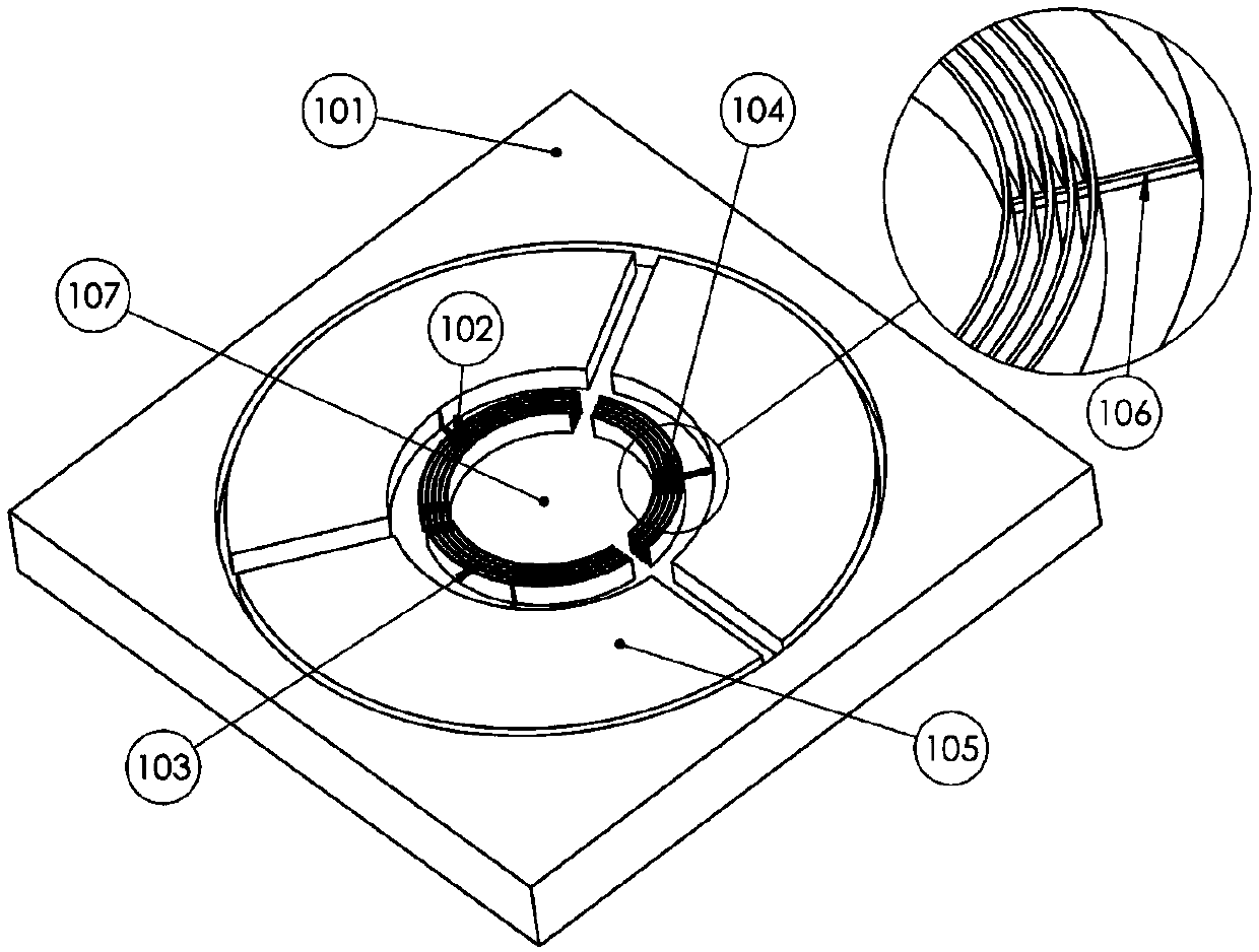
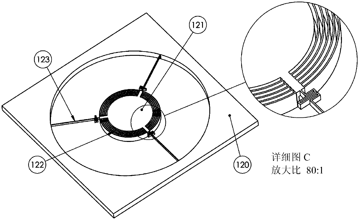
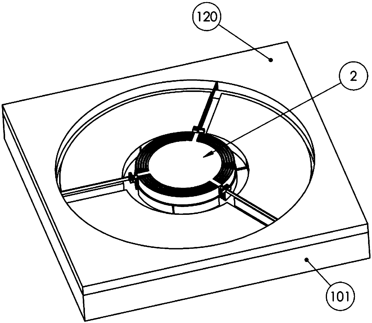
[0050] A first embodiment of the invention (3-DOF MEMS electrostatic actuator) is shown in FIG. 1 . Such as Figure 1A As shown, the fixed structure in this embodiment comprises a plurality of concentric arc-shaped teeth (pistons) 102, 103, 104, and the moving structure comprises a plurality of concentric teeth sized and designed to receive the teeth of the fixed structure. Arc-shaped groove or opening (pipe) 122 ( Figure 1B ).
[0051] The teeth or pistons are divided into three stators 102, 103, 104 arranged at 120°. Each stator includes a plurality of arcuate pistons that are vertically aligned with arcuate tubes (openings) 122 in the rotor such that they intersect each other during actuation. The three stators 102, 103, 104 are electrically isolated from each other by a buried oxide (BOX) layer 107 using an SOI wafer. However, the electrodes of each stator are electrically connected via a layer of small thickness (height) 106 above the BOX layer. The three circular is...
Embodiment approach 2
[0057] In order to avoid the limitations of Embodiment 1 in terms of biaxial rotation, the poles of the stator and rotor may be arranged in a manner that reduces the variation of the gap 126 during rotation. exist Figure 2A The pistons 204, 205, 206, 207 in this embodiment shown in , extend radially from the interior of the actuator to the exterior periphery. A parallel plate capacitor between the piston and the side of the tube extends in the radial direction of the circular plate of the actuator. Therefore, during rotation of the actuator, negligible variation in horizontal gap (g) 126 is expected for those charged piston-tube pairs that are perpendicular or nearly perpendicular to the axis of rotation. These charged piston tube pairs also produce a nearly linear relationship of torque to voltage. This is especially true when the stator layer is divided into a large number of stators, see Figure 2D (Although the figure shows a 4 stator actuator, the stator layer can be ...
Embodiment approach 3
[0059] Another embodiment of the actuator is shown in FIG. 3 . In this embodiment the pistons 304, 305, 306, 307 have a rectangular cross-section and they protrude vertically towards the rotor and extend horizontally along two in-plane axes (x and y). Each opposing stator contains a plurality of rectangular pistons also extending horizontally along two in-plane axes (x and y). The tubes 310 in the rotor are rectangular through holes and they face the pistons so that the pistons penetrate along the tubes during actuation. Compared to Embodiment 2 where the corners of the actuator are not utilized due to the circular rotor geometry, this design is more area efficient in terms of total electrode capacitance. It also utilizes an efficient spring configuration similar to that used in Embodiment 2. However, due to the change in horizontal clearance between adjacent pistons and tubes, the angle of rotation of this embodiment is limited, especially when the actuator plate is rotated...
PUM
 Abstract
Description
Claims
Application Information
 - R&D
- Intellectual Property
- Life Sciences
- Materials
- Tech Scout
- Unparalleled Data Quality
- Higher Quality Content
- 60% Fewer Hallucinations
Browse by: Latest US Patents, China's latest patents, Technical Efficacy Thesaurus, Application Domain, Technology Topic, Popular Technical Reports.
© 2025 PatSnap. All rights reserved.Legal|Privacy policy|Modern Slavery Act Transparency Statement|Sitemap|About US| Contact US: help@patsnap.com


