A power transmission system of a cutting and longitudinal flow threshing and separating device

A technology of threshing separation and power transmission, which is used in threshing equipment, cutters, agricultural machinery and implements, etc., can solve the problem that the transmission chain is easy to interfere with the side wall of the frame, the power loss of the transmission shaft is too long, and it is difficult to arrange tension. equipment and other problems, to achieve the effect of reducing power transmission distance, compact structure and low vibration

Active Publication Date: 2019-08-27
JIANGSU UNIV
View PDF7 Cites 0 Cited by
  • Summary
  • Abstract
  • Description
  • Claims
  • Application Information

AI Technical Summary

Problems solved by technology

This kind of transmission mode increases the power loss if the drive shaft is too long, and the exposure is more dangerous. In addition, the complex structure is not conducive to the layout of the whole machine, etc.
[0004] Chinese patent CN104904416A discloses a full-feed combine harvester cutting vertical flow threshing drum power transmission system. It sets the bevel gear reversing box and the transition sprocket, and the power is directly output from the bevel gear reversing box. It is transmitted to the transition sprocket with a higher installation position through the chain drive to increase the power output position and then transmitted to the longitudinal axial flow drum through the chain drive. Although this scheme simplifies the power transmission structure between the cutting flow drum and the longitudinal axial flow drum , which reduces the power transmission distance, but chain transmission is used between the transition transmission box, the bevel gear transmission box and the longitudinal axial flow roller respectively, the transmission stability is poor, the vibration and noise are large, and the phenomenon of tooth skipping and chain detachment is prone to occur, and in narrow The space is not easy to arrange tensioning device
Although this kind of transmission device has a simple structure and reduces the power transmission distance, the power output position and the power input position of this scheme are in the same horizontal plane. During practical application, the transmission chain is easy to interfere with the side wall of the frame. Generally, it is necessary to set a transition chain The wheel first raises the power transmission height and then transmits it to the longitudinal axial flow drum. The transmission stability is poor, the reliability is low, and the tensioning device is difficult to arrange. It is not suitable for the full-feed combine harvesting of the oblique cutting vertical flow type where the vertical axial flow is arranged at an angle. machine

Method used


Image

  • A power transmission system of a cutting and longitudinal flow threshing and separating device
  • A power transmission system of a cutting and longitudinal flow threshing and separating device
  • A power transmission system of a cutting and longitudinal flow threshing and separating device

Examples


Embodiment approach

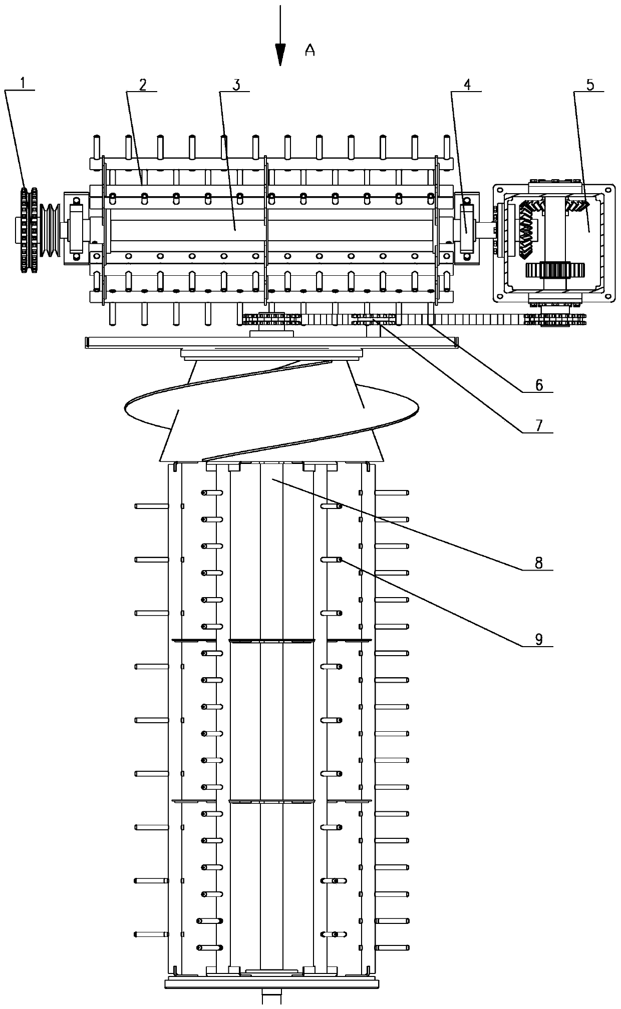
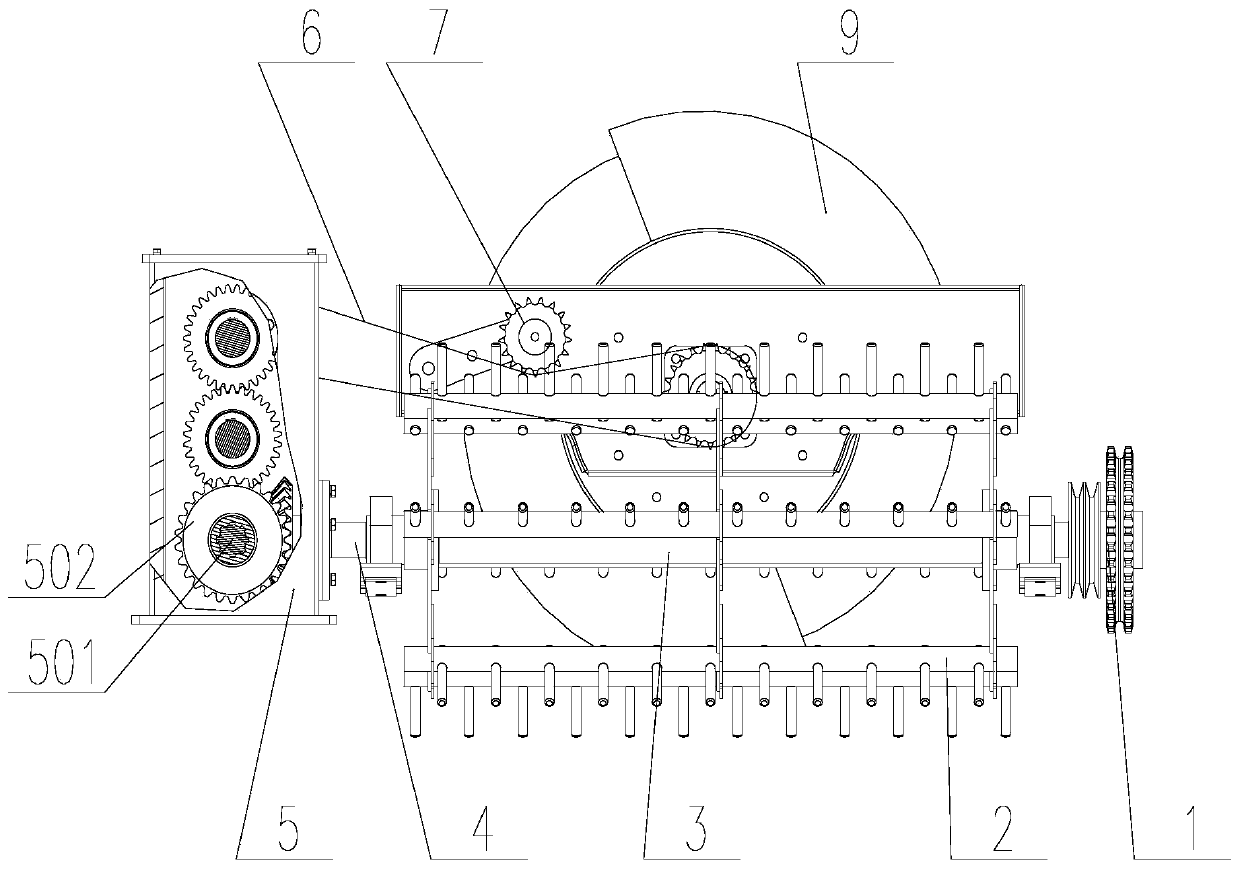
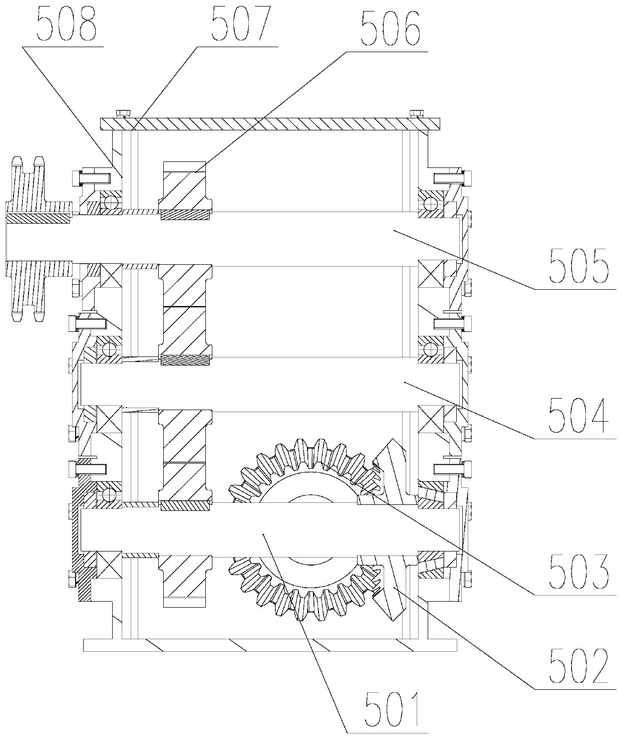
[0032] figure 1 Shown is an embodiment of the power transmission system of the tangential and longitudinal flow threshing and separating device of the present invention. The power transmission system of the tangential and longitudinal flow threshing and separating device includes a tangential flow drum 2, a gear transmission box 5, a transmission member 6, a Tightening device 7 and vertical axial flow drum 9.

[0033]The cutting flow drum 2 and the vertical axial flow drum 9 are placed perpendicular to each other; the horizontal cutting flow drum 2 is provided with a cutting flow drum shaft 3, and the two ends of the cutting flow drum shaft 3 pass through the two ends of the cutting flow drum 2 and They are respectively connected to the power input end 1 and the power output end 4, the power input end 1 is connected to the engine output shaft through a transmission structure, the cut-flow drum shaft 3 of the power output end 4 is directly inserted into the gear transmission bo...


PUM


Abstract

The invention provides a power transmission system of a longitudinal-flow-cutting, threshing and separation device. The power transmission system comprises a flow cutting roller, a gear transmission box, transmission parts and a longitudinal axial flow roller; the flow cutting roller and the longitudinal axial flow roller are placed mutually perpendicularly; a flow cutting roller shaft is arranged in the flow cutting roller which is placed horizontally, the two ends of the flow cutting roller shaft penetrate out of the two ends of the flow cutting roller and are connected with a power input end and a power output end respectively, and the flow cutting roller shaft of the power output end is directly inserted into the gear transmission box; the transmission parts are arranged in the gap which is formed between the flow cutting roller and the longitudinal axial flow roller through perpendicular staggering; the output end of the gear transmission box is connected with one end, where the longitudinal axial flow roller shaft is arranged, in the longitudinal axial flow roller. According to the power transmission system of the longitudinal-flow-cutting, threshing and separation device, power transmission is realized by the aid of the gear transmission box and one group of transmission parts. The power transmission structure between the flow cutting roller and the longitudinal axial flow roller is simplified greatly, the power transmission distance is reduced, the power transmission stability and the transmission efficiency are improved, and the vibration and the whole machine noise of a thresher rack are effectively reduced.

Description

technical field [0001] The invention belongs to the technical research field of combine harvesters, and in particular relates to a power transmission system of a cutting and longitudinal flow threshing and separating device. Background technique [0002] At present, most of the full-feed combine harvesters on the market adopt the double-drum threshing method of the vertical flow type. The threshing stroke is long and the separation area is large, which can improve production efficiency without increasing the body volume, and is adaptable to wet and difficult crops. it is good. The transmission device is an important part of the combine harvester. The stability and reliability of the transmission device directly affect the working performance and service life of the combine harvester. However, there are mainly two transmission modes for the cutting vertical flow type threshing drum of the existing full-feed combine harvester. The transmission shaft is transmitted to the lef...

Claims


Application Information

Patent Timeline
Patent Type & Authority Patents(China)
IPC IPC(8): A01F12/56A01F12/22A01D41/12
Inventor 李耀明刘晓飞徐立章唐忠伍铜言
Owner JIANGSU UNIV
Why Eureka
Try Eureka