Temperature-controlled water-cooled thin-walled round tube cladding equipment

A cladding and cold technology, applied in welding equipment, auxiliary welding equipment, metal processing equipment, etc., can solve the problems of difficult control of the surface temperature of thin-walled circular tubes, affecting the quality of cladding, and short service life, achieving real-time and effective control effects , The effect of various and flexible welding methods, timely and effective maintenance

Active Publication Date: 2018-03-23
HARBIN KENENG CLADDING TECH
View PDF8 Cites 0 Cited by
  • Summary
  • Abstract
  • Description
  • Claims
  • Application Information

AI Technical Summary

Problems solved by technology

[0003] The purpose of the present invention is to solve the short service life and frequent maintenance of the water wall, high and low temperature superheating panels, furnace bottom row and other core components in the thermal power plant boiler due to wear or corrosion, and at the same time, due to the The surface temperature of the thin-walled circular tube is difficult to control and directly affects the quality of the cladding, and then provides a temperature-controlled water-cooled thin-walled circular tube cladding equipment

Method used


Image

  • Temperature-controlled water-cooled thin-walled round tube cladding equipment
  • Temperature-controlled water-cooled thin-walled round tube cladding equipment
  • Temperature-controlled water-cooled thin-walled round tube cladding equipment

Examples


specific Embodiment approach 1

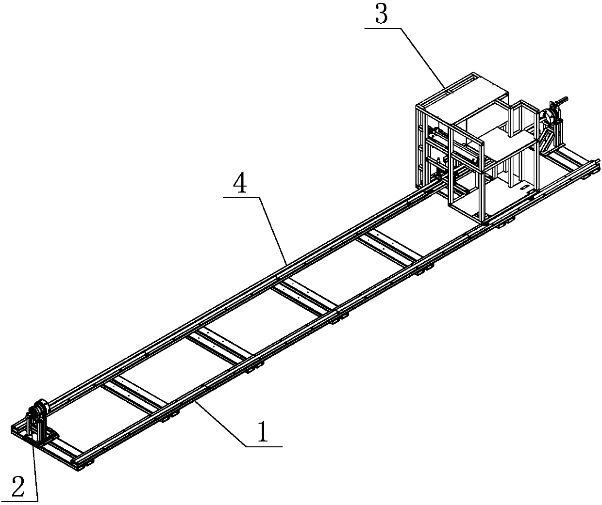
[0023] Specific implementation mode one: combine figure 1 , figure 2 , image 3 , Figure 4 , Figure 5 and Image 6 Describe this embodiment. This embodiment includes a track assembly 1, two temperature-controlled rotary water supply assemblies 2 and a fully automatic welding vehicle 3. The track assembly 1 includes an active rotary joint, a driven rotary joint and a walking track. The active rotary joint and the driven rotary joint are respectively arranged at both ends of the walking track, the fully automatic welding vehicle 3 is set on the walking track and it reciprocates along the length direction of the walking track, and one end of the processing tube 4 is set on the driven rotating track. On the joint, the other end of the processing pipe 4 passes through the automatic welding car 3 and is connected to the active rotary joint, and a temperature-controlling rotary water supply assembly 2 is respectively provided at both ends of the processing pipe 4;

[0024] Ea...

specific Embodiment approach 2

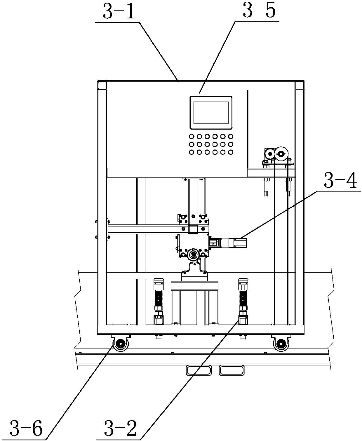
[0029] Specific implementation mode two: combination figure 1 , figure 2 , image 3 and Image 6Describe this embodiment. In this embodiment, the fully automatic welding vehicle 3 includes a frame body 3-1, a position control assembly 3-2, a linear oscillator 3-4, a control system 3-5, a workbench 3-8, a welding Application gun 3-9, at least one drive assembly and multiple mobile single wheels 3-6, the bottom of the frame body 3-1 is provided with multiple mobile single wheels 3-6, at least one drive assembly is arranged on the frame body 3-1, the workbench 3-8 is set inside the frame body 3-1, the linear oscillator 3-4 is set directly above the workbench 3-8, and the linear oscillator 3-4 is set There is a cladding gun 3-9, the tip of the cladding gun 3-9 is set facing the workbench 3-8, the control unit 3-2 is set around the workbench 3-8, and the control system 3-5 is set on the frame body 3-1 and it is electrically connected with at least one drive assembly. Other un...

specific Embodiment approach 3

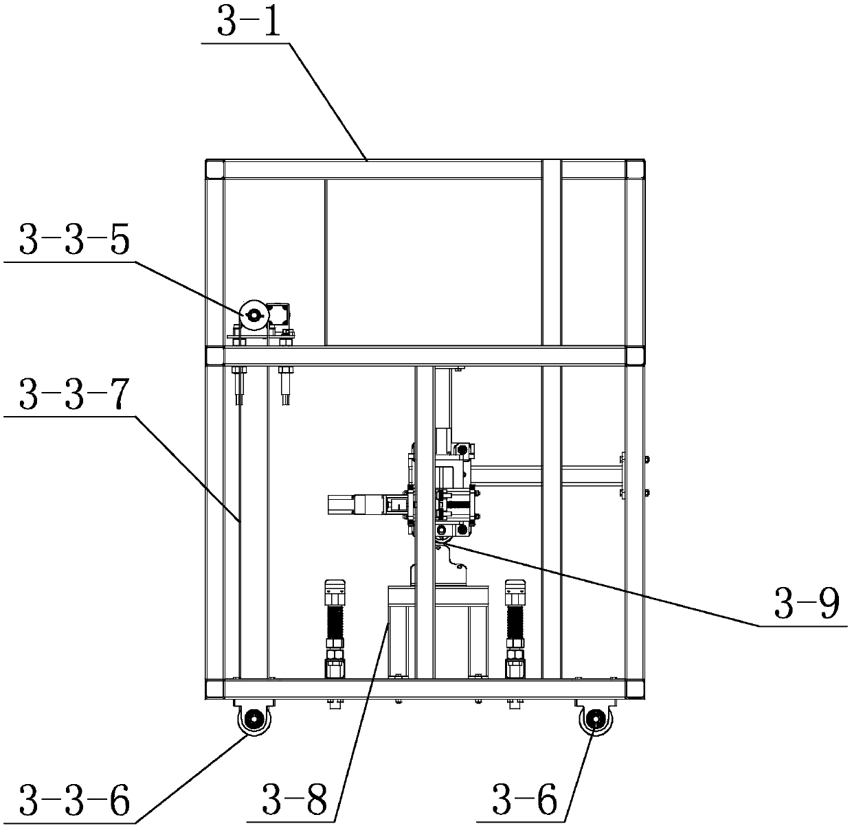
[0030] Specific implementation mode three: combination figure 1 , figure 2 , image 3 and Image 6 Describe this embodiment. In this embodiment, the drive assembly includes a rotating shaft 3-3-1, a driving gear 3-3-2, a driven gear 3-3-3, a motor 3-3-4, two upper runners 3- 3-5, two lower runners 3-3-6 and two conveyor belts 3-3-7, the motor 3-3-4 is set on the top of the frame body 3-1, the two lower runners 3- 3-6 are respectively arranged on both sides of the bottom of the frame body 3-1, the output shaft of the motor 3-3-4 is set with a driving gear 3-3-2, and the rotating shaft 3-3-1 is set with a driven gear The gear 3-3-3, the driving gear 3-3-2 is meshed with the driven gear 3-3-3, and the two ends of the rotating shaft 3-3-1 are each equipped with an upper runner 3-3-5, Each upper runner 3-3-5 is correspondingly provided with a conveyor belt 3-3-7, and each upper runner 3-3-5 corresponds to a lower runner 3-3-6, and each upper runner 3 -3-5 is connected with it...


PUM


Abstract

The invention provides a temperature control water-cooled thin wall circular pipe depositing device, and relates to a depositing device. The problem that water-cooled walls, high temperature overheating screens, lower temperature overheating screens, furnace bottom grates, and other core components in a thermal power plant boiler are short in use cycle and frequent in maintenance due to abrasion and corrosion, and the depositing quality is directly influenced due to the fact that the surface temperature of a thin wall circular pipe is difficult to control in depositing of the thin wall circular pipe can be solved. In the invention, a driving rotation joint and a driven rotation joint are arranged at two ends of a travelling rail respectively; a full-automatic depositing vehicle is arranged on the travelling rail and can do reciprocating motion in the length direction of the travelling rail; one end of a processing pipe is arranged on the driven rotation joint, and the other end of the processing pipe passes through the full-automatic depositing vehicle and is connected to the driving rotation joint; a temperature control rotation type water supply assembly is correspondingly arranged on two ends of the processing pipe each; mixing boxes successively pass through rotation joints and expansion plugs and communicate with one ends of the processing pipe corresponding to the temperature control rotation type water supply assembly. The temperature control water-cooled thin wall circular pipe depositing device can be used in depositing of the thin wall circular pipe.

Description

technical field [0001] The invention specifically relates to a temperature-controlled water-cooled thin-walled circular tube cladding equipment. Background technique [0002] Welding is to melt the anti-wear wire or anti-corrosion wire through the electrode and drop the melting point, and combine the anti-wear wire or anti-corrosion wire with the metal base material in the form of metallurgy, so as to achieve metal The wear-resistant or corrosion-resistant properties of the surface of the parent material. At present, the water wall, high and low temperature superheating panels, furnace bottom row and other core components inside the boilers of thermal power plants are facing the problems of short service life and frequent maintenance of pressure vessels caused by wear or corrosion. One of the main features of boilers in thermal power plants is that they are composed of thin-walled circular tubes due to water-cooled walls, high and low temperature superheating screens, botto...

Claims


Application Information

Patent Timeline
Patent Type & Authority Patents(China)
IPC IPC(8): B23K37/02B23K37/053
CPCB23K37/0247B23K37/053
Inventor 王俊明曹学伟李大鹏展乾邹大为王坤杨晓东赵国权
Owner HARBIN KENENG CLADDING TECH
Why Eureka
Try Eureka