Automatic grinding device and grinding method
A grinding and automatic technology, applied in the direction of grinding/polishing safety devices, grinding machines, grinding workpiece supports, etc., can solve the problems of difficult control of force, large damage to the shovel plate, low removal efficiency, etc., to achieve high grinding efficiency, Low cost and the effect of increasing the degree of automation
- Summary
- Abstract
- Description
- Claims
- Application Information
AI Technical Summary
Problems solved by technology
Method used
Image
Examples
Embodiment 1
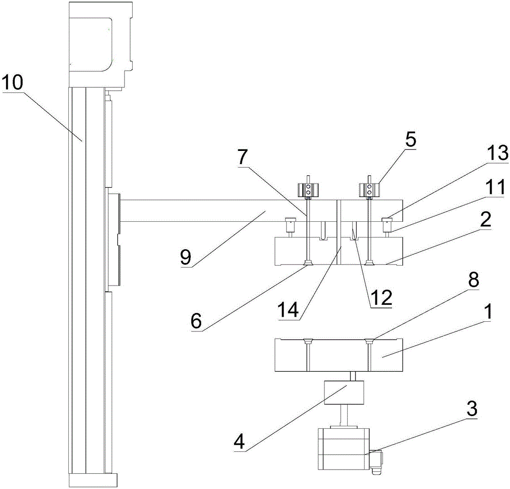
[0031] This embodiment provides an automatic grinding device, such as figure 1 As shown, it includes a first jig 1 and a second jig 2 that are relatively arranged and can perform relative rotational movement. The first jig 1 and the second jig 2 are made of Teflon, and the first jig 1 and the second jig 2 can be buckled into a complete jig, and two workpieces to be ground such as ceramics, sapphire, etc. are respectively fixed in the first jig 1 and the second jig 2, and the two workpieces The slag surface is oppositely arranged (after the workpiece is drilled and cut, a slag protrusion will be formed at the hole entrance).
[0032] Place workpieces such as ceramics between two fixtures, control the relative rotation of the two fixtures to drive the relative rotation of the two workpieces, and use the friction between the two workpieces to remove the slag. It will not cause damage to the workpiece during the process. This device solves the problems of large shovel plate loss ...
Embodiment 2
[0039] The present embodiment provides an automatic grinding method, which includes the following steps:
[0040] S1. Place two workpieces to be ground in the first jig 1 and the second jig 2 respectively, and the slag surfaces of the workpieces are set opposite to each other. Specifically, place a piece of workpiece slag face up on the first jig In 1, the second vacuum nozzle 8 is turned on to make the workpiece be absorbed and fixed, and the telescopic cylinder 5 drives the first vacuum nozzle 6 to grab another piece of workpiece. The slag of the workpiece faces downward and the workpiece is absorbed and fixed by the first vacuum nozzle 6 ;
[0041] S2. The lifting electric cylinder 10 drives the second jig 2 down to the contact between the slag surfaces of the two workpieces according to the feed rate of 0.1 mm. The moving distance is set according to the height of the slag surfaces. The force is controlled by the air spring, and the pressure sensor 13 Return pressure data...
Embodiment 3
[0044] The present embodiment provides an automatic grinding method, which includes the following steps:
[0045] S1. Place two workpieces to be ground in the first jig 1 and the second jig 2 respectively, and the slag surfaces of the workpieces are set opposite to each other. Specifically, place a piece of workpiece slag face up on the first jig In 1, the second vacuum nozzle 8 is turned on to make the workpiece be absorbed and fixed, and the telescopic cylinder 5 drives the first vacuum nozzle 6 to grab another piece of workpiece. The slag of the workpiece faces downward and the workpiece is absorbed and fixed by the first vacuum nozzle 6 ;
[0046] S2. The lifting electric cylinder 10 drives the second jig 2 down to the contact between the slag surfaces of the two workpieces according to the feed rate of 100 mm. The moving distance is set according to the height of the slag surfaces. Pressure data return;
[0047] S3, start the rotating motor 3 and the reduction box 4 to ...
PUM
 Abstract
Description
Claims
Application Information
 - R&D
- Intellectual Property
- Life Sciences
- Materials
- Tech Scout
- Unparalleled Data Quality
- Higher Quality Content
- 60% Fewer Hallucinations
Browse by: Latest US Patents, China's latest patents, Technical Efficacy Thesaurus, Application Domain, Technology Topic, Popular Technical Reports.
© 2025 PatSnap. All rights reserved.Legal|Privacy policy|Modern Slavery Act Transparency Statement|Sitemap|About US| Contact US: help@patsnap.com

