Mixed flow water turbine blade machining device

A processing device and water turbine technology, applied in metal processing equipment, reaction engines, mechanical equipment, etc., can solve the problems of high production cost, high difficulty of finishing, and inconvenience, so as to improve processing efficiency, reduce labor cost, and guarantee The effect of stability

Inactive Publication Date: 2017-05-10
吴基玄
View PDF6 Cites 2 Cited by
  • Summary
  • Abstract
  • Description
  • Claims
  • Application Information

AI Technical Summary

Problems solved by technology

The surface of the blades of the water turbine is generally arc-shaped, and its shape is cast. The surface of the water turbine blades cast is relatively rough, so it needs to be placed on the machine tool for cutting and finishing. When cutting, it is necessary to set the cutting track of the tool so that the cutting track of the tool coincides with the arc surface of the blade, otherwise the surface of the machined blade is not smooth and cannot meet the technical requirements of the blade. Therefore, the finishing of the turbine blade on the machine tool The difficulty is high, and the control structure of the tool is relatively complicated, and some processing plants with poor technical equipment generally use the method of manual grinding with sandpaper to finish the surface of the turbine blade, while manual processing is very inefficient and the production cost is high. Very inconvenient, for this reason, we propose a Francis turbine blade processing device to solve the above problems

Method used


Image

  • Mixed flow water turbine blade machining device
  • Mixed flow water turbine blade machining device

Examples


Embodiment Construction

[0013] The following will clearly and completely describe the technical solutions in the embodiments of the present invention with reference to the accompanying drawings in the embodiments of the present invention. Obviously, the described embodiments are only some, not all, embodiments of the present invention.

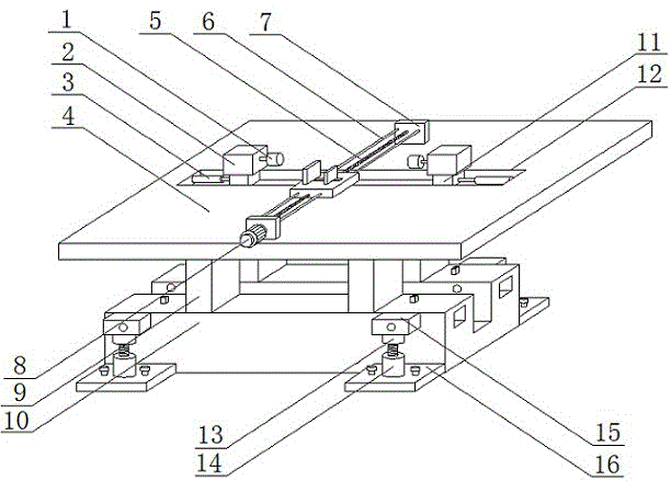
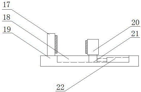
[0014] refer to Figure 1-2 , a Francis turbine blade processing device, comprising a base 10, which acts as a bearing, the upper end of the base 10 is fixed with a plurality of supporting blocks 9, the upper end of the supporting blocks 9 is fixed with a bearing plate 4, and the upper end of the supporting plate 4 is provided with a first The chute 12, the first cylinder 3 is fixed on the side walls at both ends of the first chute 12, and two first sliders 11 are installed in the first chute 12, and the first slider 11 passes through the first cylinder 3 The piston rod telescopically slides in the first chute 12, the end of the piston rod of the first cylinder 3 is ...


PUM


Abstract

The invention discloses a mixed flow water turbine blade machining device. The mixed flow water turbine blade machining device comprises a base; a plurality of supporting blocks are fixed to the upper end of the base; a bearing plate is fixed to the upper ends of the supporting blocks; a first sliding groove is formed in the upper end of the bearing plate; first air cylinders are fixed to the side walls of the two ends in the first sliding groove; two first sliding blocks are mounted inside the first sliding groove; the tail ends of piston rods of the first air cylinders are fixedly connected with one sides of the first sliding blocks correspondingly; protective cases are fixed to the upper ends of the first sliding blocks correspondingly; and second driving devices are disposed in the protective cases correspondingly. By means of combination of a screw rod, driving devices, the first air cylinders and grinding wheels, automatic grinding and conveying of water turbine blades are achieved; by means of combination of upper fixing blocks, connection blocks and damping springs, the damping function is achieved, and the machining stability is ensured; and machining is facilitated, the machining efficiency is improved, the labor cost is greatly reduced, the machining stability is guaranteed, and the mixed flow water turbine blade machining device is suitable for being popularized.

Description

technical field [0001] The invention relates to the technical field of water turbine processing, in particular to a mixed flow type water turbine blade processing device. Background technique [0002] A water turbine is a power machine that converts the energy of water flow into rotating mechanical energy. It is widely used in hydropower stations to drive generators to generate electricity. In hydropower stations, the water in the upstream reservoir is led to the water turbine through the diversion pipe to drive the runner of the water turbine. Rotate to drive the generator to generate electricity. The water flowing from the upstream reservoir to the runner of the turbine needs to pass through the water guide mechanism and then enter the runner. The main function of the water guide mechanism is to adjust the flow of the turbine according to the change of the load of the power system, so as to meet the requirements of the system for the output of the unit, form and change Th...

Claims


Application Information

Patent Timeline
IPC IPC(8): B24B19/14B24B41/06B24B41/00F03B3/12
CPCB24B19/14B24B41/005B24B41/06F03B3/12Y02E10/20Y02P70/10
Inventor 吴基玄吴平
Owner 吴基玄
Why Eureka
Try Eureka