a drilling tool

A technology for drilling tools and blades, which is applied in drilling tool accessories, drilling/drilling equipment, and tools for lathes, etc. It can solve problems such as difficult cost control, unsustainable enterprise site, and edge flanging of holes. Achieve the effect of meeting continuous production, reducing development costs and saving space

Active Publication Date: 2018-07-10
YANFENG PLASTIC OMNIUM AUTOMOTIVE EXTERIOR SYST
View PDF10 Cites 1 Cited by
  • Summary
  • Abstract
  • Description
  • Claims
  • Application Information

AI Technical Summary

Problems solved by technology

Obviously, this kind of "special purpose" equipment makes the enterprise site unsustainable, and the cost is difficult to control
[0003] In addition, the existing special-purpose drilling machines inevitably have problems such as hole edge flanging, burrs and / or fuses, and can only meet the production requirements of process holes with low surface quality requirements or surface can be covered
Moreover, the existing special-purpose drilling machines have the problem of difficult waste disposal, which not only causes quality problems due to the friction between the drilling waste and the edge of the product hole due to the difficulty in separating the drilling waste, but more importantly, the subsequent drilling cannot be completed because the waste does not fall off on the tool. conduct

Method used


Image

  • a drilling tool
  • a drilling tool
  • a drilling tool

Examples


Embodiment Construction

[0020] Below in conjunction with the drawings, preferred embodiments of the present invention are given and described in detail.

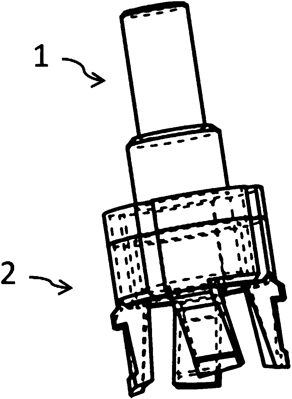
[0021] Such as Figure 1-Figure 3 As shown, the drilling tool according to the present invention includes a handle 1 and a cutter body 2 extending around a central axis, wherein the handle 1 is formed of an alloy material, and the cutter body 2 is formed of a cemented carbide material. Or formed into one by welding, such as figure 1 shown. In particular, the present invention uses hard materials to form the cutter body 2, which solves the problems of stress wear and material corrosion of the cutter edge, and ensures the cutting stability of the drilling cutter during the drilling process.

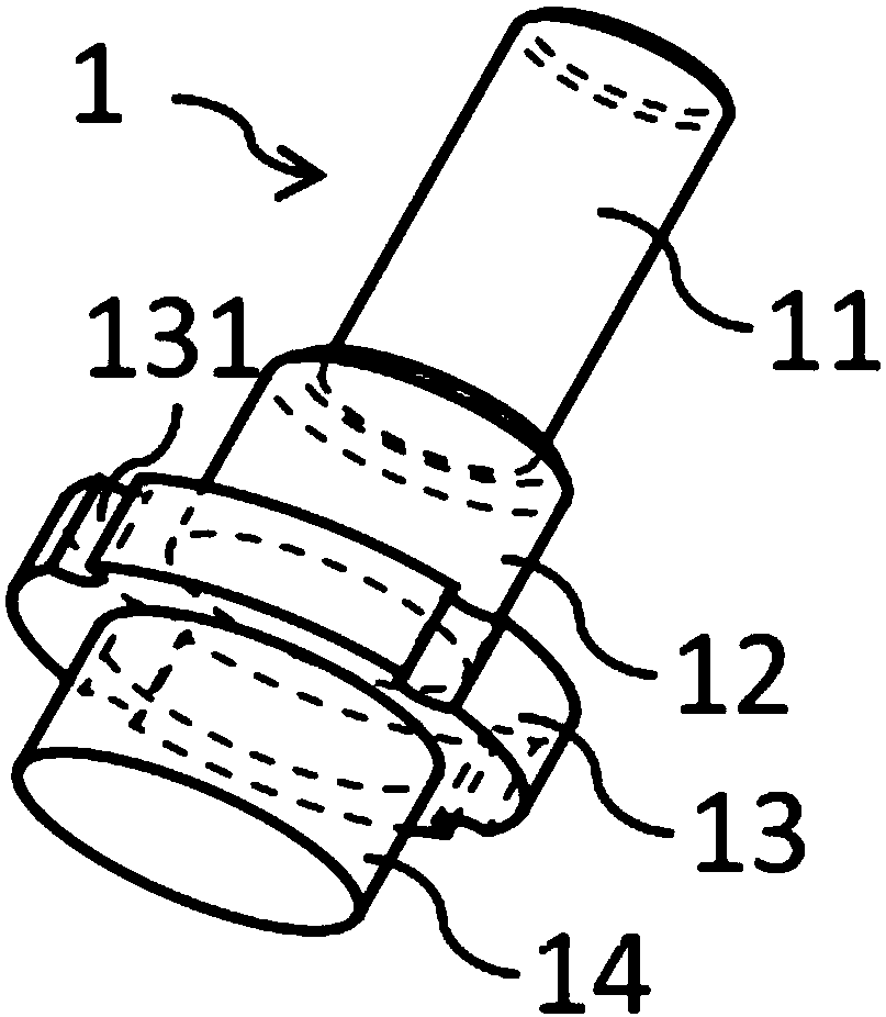
[0022] Such as figure 2 As shown, the tool holder 1 includes a first cylindrical section 11, a second cylindrical section 12, a third cylindrical section 13 and a fourth cylindrical section 14 arranged coaxially in sequence, wherein the diameter of the first...


PUM


Abstract

The invention relates to a drilling tool, comprising a shank and a tool body which are connected to each other and extend around a central axis. The tool body includes a ring segment and a blade structure, the ring segment and the tool handle are connected and fixed, and the blade structure includes a Four evenly spaced circumferentially spaced cutting edges extend from the ring segment, the four cutting edges are arranged left-handed around the central axis, respectively extending from the circular ring segment away from the central axis and away from the shank, each cutting edge comprising a circumferential The outer surface of the blade and the inner surface of the blade are extended, the end of each blade away from the annular segment is provided with a leading edge extending radially outward from the outer surface of the blade, and the other end adjacent to the annular segment is provided with a front edge from the outer surface of the blade. The outer surface of the blade extends radially outward of the rear edge, and a hollow groove is formed between the front edge and the rear edge. The drilling tool of the invention is matched with the robot to form flexible drilling equipment, so as to meet the drilling requirements of different products, which can not only effectively save the factory site of the enterprise, but also reduce the development cost of the equipment.

Description

technical field [0001] The invention relates to the drilling of automotive exterior plastic parts, and more particularly relates to a drilling tool. Background technique [0002] Drilling operations are often involved in automotive exterior plastic parts, such as forming radar holes (holes for installing radars), cleaning holes (holes for installing automatic retractable water spray cleaning devices) and assembly holes ( holes for mounting trim), etc. In the prior art, these drilling operations are performed by a dedicated drilling machine, that is, one drilling machine is adapted to one type of product (workpiece). Obviously, this kind of "special purpose" equipment makes the enterprise site unsustainable, and the cost is difficult to control. [0003] In addition, existing special-purpose drilling machines inevitably have problems such as hole edge flanging, burrs and / or fuses, and can only meet the production requirements of process holes with low surface quality requir...

Claims


Application Information

Patent Timeline
Patent Type & Authority Patents(China)
IPC IPC(8): B26F1/16B23B51/04
CPCB26F1/16B23B2200/325B23B51/04B26D7/1854B23B2226/61
Inventor 李育弟金启扬
Owner YANFENG PLASTIC OMNIUM AUTOMOTIVE EXTERIOR SYST
Why Eureka
Try Eureka