Swirl combustion chamber of rotor engine

A rotary engine and combustion chamber technology, which is applied in combustion engines, machines/engines, internal combustion piston engines, etc., can solve the problems such as the inability of the flame to propagate in the reverse direction, the flow rate of the mixture is large, and the misfire rate is increased. The effect of sufficient mixing and reduced airflow

Inactive Publication Date: 2017-05-10
JIANGSU UNIV
View PDF6 Cites 3 Cited by
  • Summary
  • Abstract
  • Description
  • Claims
  • Application Information

AI Technical Summary

Problems solved by technology

However, since the combustion chamber of the rotary engine rotates together with the rotor, after being compressed to the top dead center, the vortex in the cylinder is completely broken into a unidirectional flow following the direction of the rotor movement, and the average turbulent kinetic energy is reduced, so the combustion rate is low, and the combustion process often lasts until In the expansion stage, the constant volume degree is poor, resulting in low thermal efficiency
The high-speed airflow also accelerates the loss of ignition energy, which increases the misfire rate, and the fuel is discharged into the atmosphere without burning, which will cause a large amount of hydrocarbon emissions
In addition, because the mixture gas velocity is much greater than the flame propagation velocity, it is difficult for the flame to propagate in reverse, and the flame is easily quenched when propagating to the tail of the combustion chamber. The narrow and slender combustion chamber intensifies the quenching phenomenon, and the emission of hydrocarbons and carbon monoxide increases.
[0003] In order to overcome the above shortcomings, people continue to improve the structure of the combustion chamber. At present, the mainstream design of the combustion chamber is to set up pits on the rotor. The pit designs are roughly divided into three categories, the middle pit, the front pit and the rear pit. When the central pit combustion chamber is compressed at the top dead center, due to the large flow cross-sectional area near the short axis, the airflow velocity is relatively low, which can stabilize the flame in the pit, but the airflow velocity is still greater than the flame propagation velocity, and the flame still cannot Reverse propagation, the mixture at the tail of the combustion chamber cannot be fully combusted. Although the problem of unburned hydrocarbons at the tail can be solved by using front and rear double spark plugs, this will make the structure complicated, and the rear spark plug is in a non-equal pressure zone, and the leakage between adjacent combustion chambers Air problem is serious
The pre-pit combustion chamber reduces the content of the mixture gas with a slow combustion speed by reducing the volume of the tail of the combustion chamber to make the combustion timely, thereby alleviating the problem of unburned hydrocarbon emissions. However, due to the small flow cross-sectional area near the short axis, the mixture flow rate Large, the flame front is not easy to stabilize
The arrangement of rear pits and rear spark plugs also has the problem of air leakage between adjacent combustion chambers, and most of the mixture must flow through the short axis, resulting in large flow loss and heat transfer loss
In addition to changing the rotor structure, there is also a plan to stabilize the rear flame front by opening fire slots on the cylinder profile, but the fire slots need to have a certain width, and the radial seal of the rotor is a linear seal, so this will increase air leakage
[0004] Although these solutions can improve engine performance to a certain extent, they cannot fundamentally achieve efficient combustion because the unidirectional flow field has not changed.

Method used


Image

  • Swirl combustion chamber of rotor engine
  • Swirl combustion chamber of rotor engine
  • Swirl combustion chamber of rotor engine

Examples


Embodiment Construction

[0023] The present invention will be further described below in conjunction with the accompanying drawings and specific embodiments, but the protection scope of the present invention is not limited thereto.

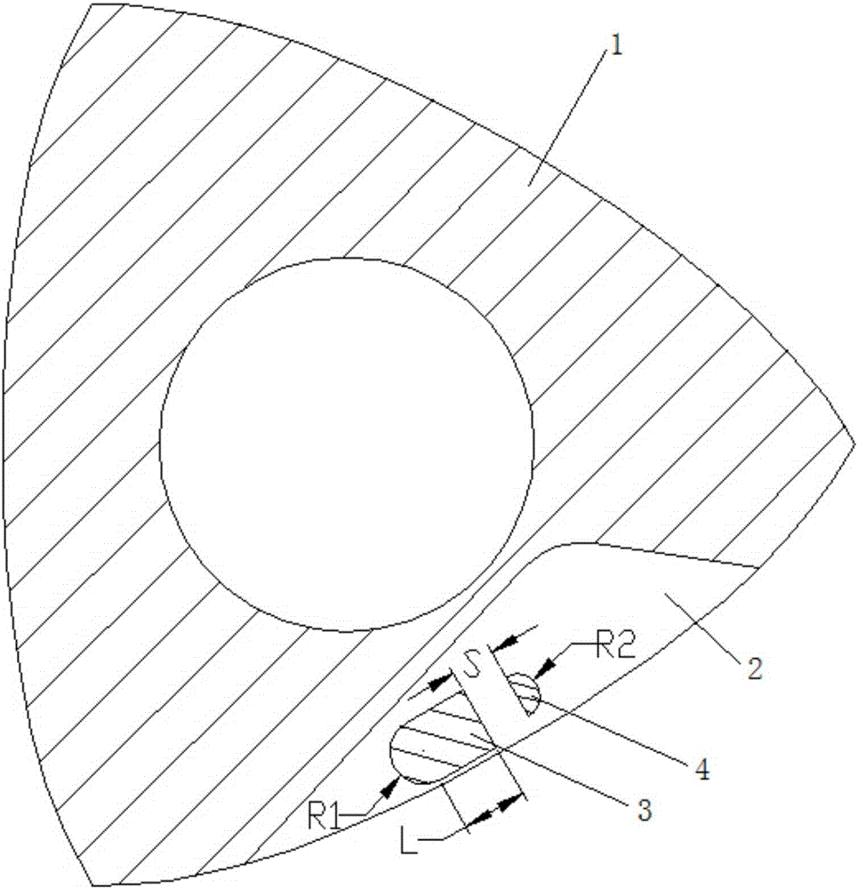
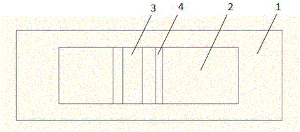
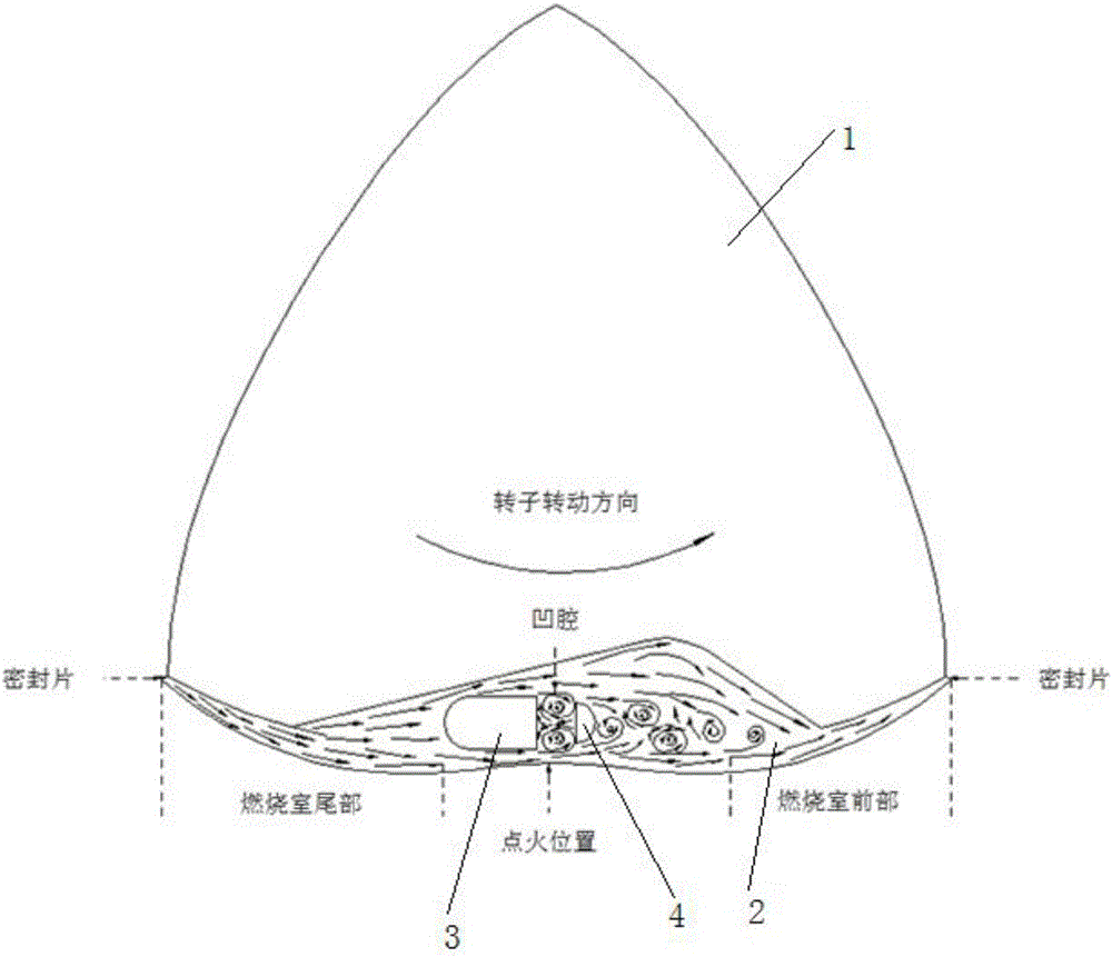
[0024] Such as figure 1 , figure 2 As shown, in the vortex combustion chamber of the rotor 1 engine according to the present invention, the front blunt body 3 and the rear blunt body 4 that are parallel to each other and perpendicular to the end surface of the rotor 1 are arranged in the cavity 2 of the rotor 1 along the movement direction of the rotor 1. , both ends of the front blunt body 3 and the rear blunt body 4 extend to the inner end surface of the rotor 1 pit 2, there is a gap between the front blunt body 3 and the rear blunt body 4, so that the front blunt body 3, the rear blunt body The blunt body 4 and the inner wall of the pit 2 of the rotor 1 enclose a cavity. The positions of the front blunt body 3 and the rear blunt body 4 in the pit 2 are such that whe...


PUM


Abstract

The invention provides a swirl combustion chamber of a rotor engine. Two blunt bodies perpendicular to the end face direction are arranged front and back in a concave pit of a wankel rotor in the motion direction of the rotor, the two ends of each blunt body are fixedly connected with the inner end face of the concave pit of the rotor, the section of the front blunt body is composed of a semicircle and a rectangle using the diameter of the semicircle as one edge, the section of the back blunt body is in a semicircle shape, the diameter of the back blunt body semicircle is parallel to one edge of the front blunt body rectangle, a cavity is formed between the diameter of the back blunt body semicircle and the edge of the front blunt body rectangle, and the radius of the front blunt body semicircle is larger than that of the back blunt body. By the additional arrangement of the blunt bodies in the concave pit of the rotor of the rotor engine, a backflow region is formed in a combustion chamber, the formation of gas mixture and flame propagation are accelerated, and the high combustion efficiency is achieved.

Description

technical field [0001] The invention belongs to the technical field of internal combustion engine combustion, and in particular relates to an improved design of a combustion chamber in which front and rear blunt bodies are added in a pit of a combustion chamber of a rotary engine to form a backflow vortex to improve the combustion efficiency of the rotary engine. Background technique [0002] Compared with reciprocating piston engines, rotary engines have no valve mechanism and reciprocating mechanism, and have the advantages of simple structure, stable movement, low vibration and noise, and good high-speed performance. Therefore, they are widely used in military applications such as drones and small portable generators. field and civilian fields such as range extenders. However, since the combustion chamber of the rotary engine rotates together with the rotor, after being compressed to the top dead center, the vortex in the cylinder is completely broken into a unidirectiona...

Claims


Application Information

Patent Timeline
Patent Type & Authority Applications(China)
IPC IPC(8): F02B55/14
CPCF02B55/14
Inventor 潘剑锋陶佳宇范宝伟刘杨先
Owner JIANGSU UNIV
Why Eureka
Try Eureka