Drill and drill head

A drill bit and head technology, which is applied in the field of drill bits and drill bit heads, can solve the problems of high cutting resistance, short tool life, and inability to fully ensure the amount of regrinding, and achieve the effects of improving processing efficiency and suppressing cutting resistance

Inactive Publication Date: 2017-05-10
MITSUBISHI MATERIALS CORP
View PDF14 Cites 3 Cited by
  • Summary
  • Abstract
  • Description
  • Claims
  • Application Information

AI Technical Summary

Problems solved by technology

That is, drilling is performed while expanding the machining hole of the workpiece material in the radial direction, so the diameter shrinkage phenomenon (springback) of the machining hole occurs after machining, and it is difficult to ensure the machining accuracy of the hole.
Specifically, when drilling with a drill, the inner circumference of the processed hole is pressed radially outward to elastically deform it, and the inner circumference of the processed hole recovers from deformation after processing, resulting in a smaller hole diameter than expected, and it is impossible to ensure Inner diameter accuracy
[0016] In addition, since the cutting edge has a long length, the cutting resistance during drilling is large
In addition, since the length of the cutting edge in the direction of the drill axis is long, the stroke (processing length in the direction of drill transmission) during drilling is long, which affects processing efficiency (productivity).
[0017] In the drill of Patent Document 4, the small-diameter portion and the large-diameter portion are aligned along the axial direction of the drill, so the stroke during drilling is long, which affects processing efficiency (productivity).
[0018] In addition, the small-diameter part is short in the axial direction of the drill, so the amount of regrinding cannot be ensured sufficiently, and the tool life is short
[0019] The drill in Patent Document 5 is formed such that the radially outer end of the cutting edge (tip edge) protrudes toward the front end of the drill relative to the portion other than the end, so cutting resistance acts on the end to a large extent, and wear tends to occur. and defect

Method used


Image

  • Drill and drill head
  • Drill and drill head
  • Drill and drill head

Examples


no. 1 Embodiment approach >

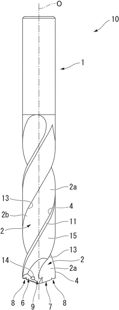
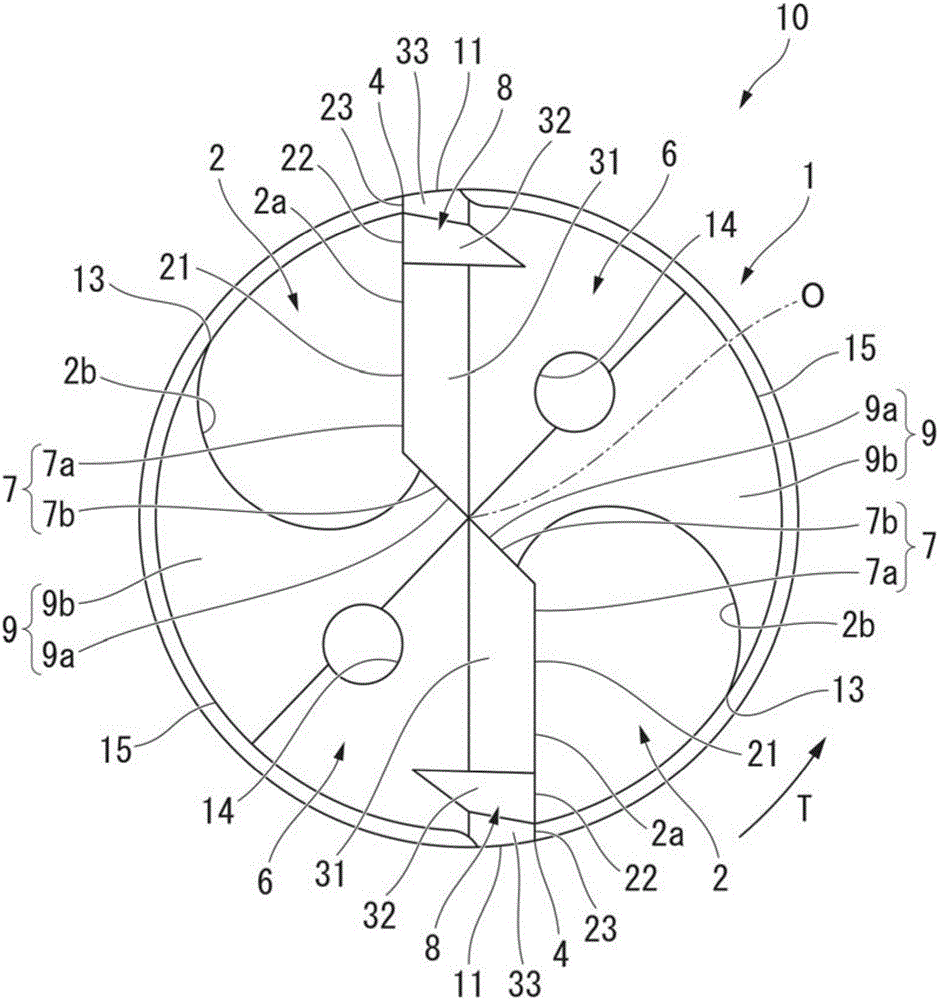
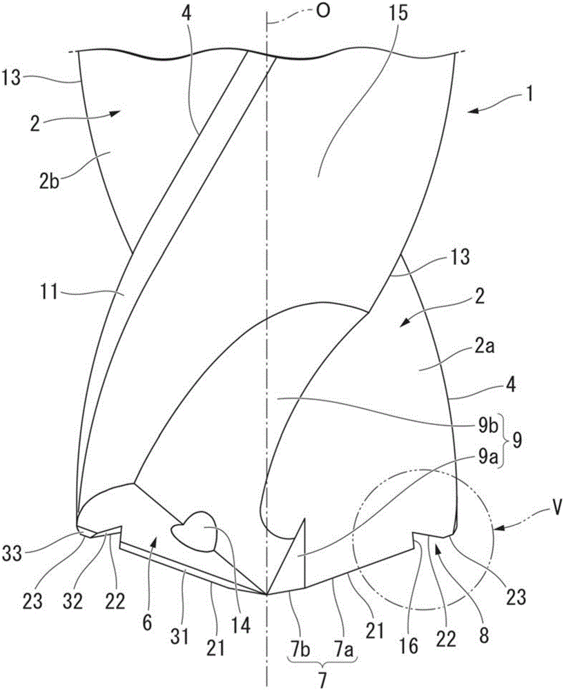
[0164] Below, refer to Figure 1 to Figure 6 The drill 10 according to the first embodiment of the present invention will be described.

[0165] like Figure 1 ~ Figure 4As shown, the drill 10 of the present embodiment has a drill body 1 having a substantially cylindrical shape centered on an axis O and formed of a hard material such as cemented carbide. The base end side portion in the axis O direction of the drill body 1 is a cylindrical shank, and the front end side portion in the axis O direction is a blade portion having a cutting edge. In addition, the cutting edge includes a front end edge 7 and an outer peripheral edge 4 which will be described later.

[0166] In the drill 10, the shank of the drill body 1 is detachably mounted on the spindle of the machine tool or the three-jaw chuck of the drill press and electric drill, etc., and rotates along the drill rotation direction T around the axis O, and moves to the front end along the axis O direction. side( figure 1...

no. 2 Embodiment approach >

[0274] Next, refer to Figure 11 to Figure 15 , the drill 30 according to the second embodiment of the present invention will be described.

[0275] In addition, the detailed description of the same constituent elements as those of the first embodiment described above will be omitted, and only the differences will be mainly described below.

[0276] The drill 30 of the present embodiment is provided with a fourth front edge 24 instead of the ridge line 16 described in the aforementioned drill 10 , which constitutes a part of the front edge 7 and functions as a cutting edge. Furthermore, the shape of the recessed portion 38 is different from the shape of the recessed portion 8 described in the first embodiment by forming the fourth front end edge 24 , and the fourth flank 34 is formed in the recessed portion 38 of the present embodiment.

[0277] Specifically, in this embodiment, if Figure 12 to Figure 15 As shown, the radial inner end of the second front end cutting edge 22...

no. 3 Embodiment approach >

[0379] Next, refer to Figure 22A ~ Figure 25 , the drill 60 according to the third embodiment of the present invention will be described.

[0380] In addition, in the following, the detailed description of the same constituent elements as those of the aforementioned reference example will be omitted, and only the differences will be mainly described.

[0381] [Differences from the above reference example]

[0382] The main difference between the drill 60 of this embodiment and the drill 50 described in the aforementioned reference example lies in the shape of the tip of the drill body 1 (the tip surface 26 , the tip edge 17 ).

[0383] 〔Front side〕

[0384] Figure 22A and Figure 22B In the shown drill 60 of this embodiment, the front end surface (front flank) 26 of the drill body 1 is provided with a first relief surface 31 , followed by a first front edge 21 to a first front edge 21 described later from the front end edge 17 . 4. Among the front end cutting edges 24, ...


PUM


Abstract

A drill is provided with a drill body that is rotated around the axial line, chip-discharging flutes (2) formed on the periphery of the drill body, and tip edges (7) formed on the intersection ridges between the chip-discharging flutes (2) and the tip surfaces of the drill body. The tip edges (7) have a first lip (21), which extends toward the base end of the axial direction as one follows the lip radially outward, and a second lip (22), which is disposed outside of the first lip (21) in the radial direction. The second lip (22) extends toward the tip in the axial direction or is perpendicular to the axis line as one follows the lip radially outward. The radially inside end of the second lip (22) is disposed on the axially base end side of the radially outside end of the first lip (21), and the radially outside end of the second lip (22) is disposed on a virtual extension (VL) of the first lip (21) that extends radially outward.

Description

technical field [0001] The present invention relates to a drill and a drill head for drilling a workpiece material such as CFRP (carbon fiber reinforced resin) or a composite material obtained by laminating metal plates such as titanium or aluminum on the CFRP; The head is detachably attached to the front end portion of the tool body of the indexable insert drill or is attached to the front end portion of the tool body in a fixed state by brazing or the like. [0002] This application claims to be based on the patent application No. 2014-197097 filed in Japan on September 26, 2014, the patent application No. 2015-150810 filed in Japan on July 30, 2015, and the patent application filed in Japan on September 24, 2015 Priority of No. 2015-187316, the contents of which are incorporated herein. Background technique [0003] Conventionally, drilling with a drill has been performed on workpiece materials such as CFRP (Carbon Fiber Reinforced Resin) used for aircraft parts, or comp...

Claims


Application Information

Patent Timeline
Patent Type & Authority Applications(China)
IPC IPC(8): B23B51/00
CPCB23B51/00B23B51/02B23B51/06B23B2226/275B23B2251/04B23B2251/085B23B2251/14B23B2251/18B23B2251/44B23B2251/043B23B2251/204B23B2251/40
Inventor 马渕雅行成毛康一郎高桥宗平日比贵大山本匡柳田一也
Owner MITSUBISHI MATERIALS CORP
Why Eureka
Try Eureka