A kind of magnet vertical press molding method and its molding equipment

A technology of press forming and forming equipment, applied in the field of magnet vertical press forming method and forming equipment, can solve the problems of waste of cutting loss, unstable quality of magnets in the same batch, uneven distribution of forming materials, etc. The effect of stabilizing product quality and improving processing efficiency

Active Publication Date: 2019-05-03
NINGBO XINFENG MAGNET IND
View PDF9 Cites 0 Cited by
  • Summary
  • Abstract
  • Description
  • Claims
  • Application Information

AI Technical Summary

Problems solved by technology

These are the main permanent magnet materials on the market, and some are eliminated due to the original production process or cost, which cannot be widely used, such as Cu-Ni-Fe (copper-nickel-iron), Fe-Co-Mo (iron-cobalt-molybdenum) , Fe-Co-V (iron cobalt vanadium), MnBi (manganese bismuth)
[0009] The production of small permanent magnets, in the prior art, is formed by cutting large magnets after they are formed. After cutting, not only need to cut and trim again, but also need to consider the cutting loss in the form of cutting In addition, the quality of the same batch of magnets is unstable due to the uneven distribution of molding materials after the large block structure is cut into small pieces.

Method used


Image

  • A kind of magnet vertical press molding method and its molding equipment
  • A kind of magnet vertical press molding method and its molding equipment

Examples


Embodiment 1

[0024] In the compression molding method of this embodiment, the mold used for the compression has a molding structure, and the magnetic blank is formed in the molding structure, and is pressed in a magnetic field to realize compression molding, wherein the direction of the magnetic field is perpendicular to the direction of the pressure.

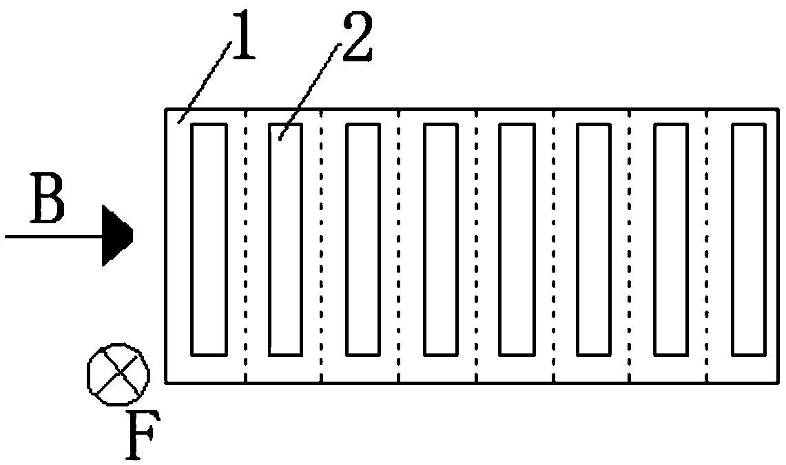
[0025] Different from the above embodiments including but not limited to, the molded structure has a plurality of basic pressure chambers (that is, the number of basic pressure chambers is one, two, three, four, five and more), and in the molded structure A plurality of mutually independent basic pressure chambers are formed in one direction and stacked into a row of unit structures (that is, the number of mutually independent basic pressure chambers formed on a row of unit structures is one, two, three, four, five and more multiple), and at least one column of unit structures is set in the molded structure (ie, the number of unit structures...

Embodiment 2

[0034] The forming equipment in this embodiment includes a mould. The mold has at least a female mold and a male mold. The magnetic blank is pressed and magnetized in the mold cavity formed by the female mold and the male mold. The direction of the magnetizing magnetic field is related to the pressing pressure The direction is vertical, the mold has a plurality of mutually independent mold cavities (that is, the number of mold cavities is one, two, three, four, five and more), and the mold cavity is formed in one direction of the mold with multiple Independent mold cavities (that is, the number of mold cavities in one direction of the mold is one, two, three, four, five and more) and stacked into a mold unit structure, while the mold is set There is at least one column of mold unit structures (i.e. the number of mold unit structures is one, two, three, four, five and more columns): when the mold unit structure has multiple columns (i.e. the number of mold unit structures is two...


PUM


Abstract

The invention discloses a magnet vertical press forming method. A mold adopted for pressing is of a mold pressing structure, a magnet blank is formed in the mold pressing structure, and press forming is realized as the pressure is applied to the magnet blank in a magnetic field, wherein the direction of the magnetic field is perpendicular to that of the pressure. According to the magnet vertical press forming method, with adoption of a mode that the direction of the magnetic field is perpendicular to that of the pressure, stress extrusion and magnetic powder magnetization can be mutually adapted in the magnetization pressing process, so that a magnetic field configuration with good magnetization configuration is obtained when a good magnet dense structure is acquired, and the efficiency of magnet processing forming and the quality of a magnet product are improved.

Description

technical field [0001] The invention relates to a magnet compression molding method and equipment using the method, in particular to a magnet vertical compression molding method and molding equipment. Background technique [0002] From the perspective of the development history of permanent magnet materials, the carbon steel used at the end of the 19th century had a magnetic energy product (BH)max (a physical quantity that measures the magnetic energy density of a permanent magnet) less than 1MGOe (mega-high), while the mass-produced Nd-Fe abroad -B permanent magnet material, the magnetic energy product has reached more than 50MGOe. Over the past century, the remanence Br of the material has increased very little, and the increase in energy product is due to the increase in coercive force Hc. The improvement of coercivity is mainly due to the understanding of its nature and the discovery of high magnetocrystalline anisotropy compounds, as well as the progress of preparation...

Claims


Application Information

Patent Timeline
Patent Type & Authority Patents(China)
IPC IPC(8): B22F3/03H01F41/02
CPCB22F3/03H01F41/0266
Inventor 韦立立戴峤笠毛宗富翁苗飞黄国光
Owner NINGBO XINFENG MAGNET IND
Why Eureka
Try Eureka