Safety and energy-saving combustion furnace

A kind of stove, safe technology, applied in the direction of household stove/stove, lighting and heating equipment, solid heating fuel, etc., can solve the problems of hemoglobin can not combine with oxygen, body tissue hypoxia, carbon monoxide poisoning, etc., to achieve rapid and full combustion reaction , Promote complete combustion, increase the effect of air volume

Inactive Publication Date: 2017-05-17
卢永强
View PDF4 Cites 0 Cited by
  • Summary
  • Abstract
  • Description
  • Claims
  • Application Information

AI Technical Summary

Problems solved by technology

The structure of the existing domestic coal stove is generally as follows figure 1 As shown, the furnace body 1 is hollow to form a furnace 4, a furnace grate 2 is arranged in the furnace 4, honeycomb briquettes 3 are placed on the furnace grate 2 to burn, and a slag chamber 5 is arranged at the lower end of the furnace grate 2, and the slag chamber 5 is connected to the air inlet 6. There is one biggest disadvantage of this traditional coal stove. When the honeycomb coal is not fully burned, it will produce a large amount of carbon monoxide gas. Causes hypoxia in the body tissue, leading to suffocation and death; from the beginning of liberation to the present, there are countless cases of carbon monoxide poisoning deaths caused by improper use of coal stoves in rural areas in China. In addition to requiring indoor ventilation when using coal stoves, So far, there is no good solution; but in order to save coal and prolong the burning time, when farmers do not need to cook or need heating, they will increase the burning duration and reduce the burning temperature by reducing the amount of air entering the honeycomb coal. , but doing so will further promote the production of carbon monoxide and increase the toxicity of carbon monoxide

Method used


Image

  • Safety and energy-saving combustion furnace
  • Safety and energy-saving combustion furnace
  • Safety and energy-saving combustion furnace

Examples


Embodiment Construction

[0028] In order to enable those skilled in the art to better understand the technical solution of the present invention, the present invention will be described in detail below in conjunction with the accompanying drawings. The description in this part is only exemplary and explanatory, and should not have any limiting effect on the protection scope of the present invention. .

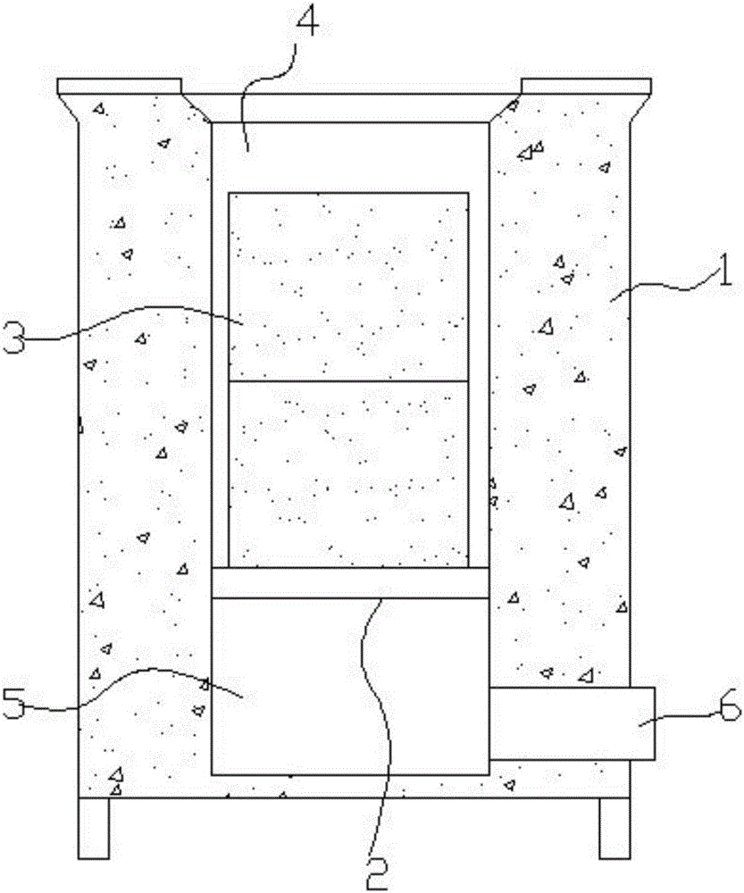
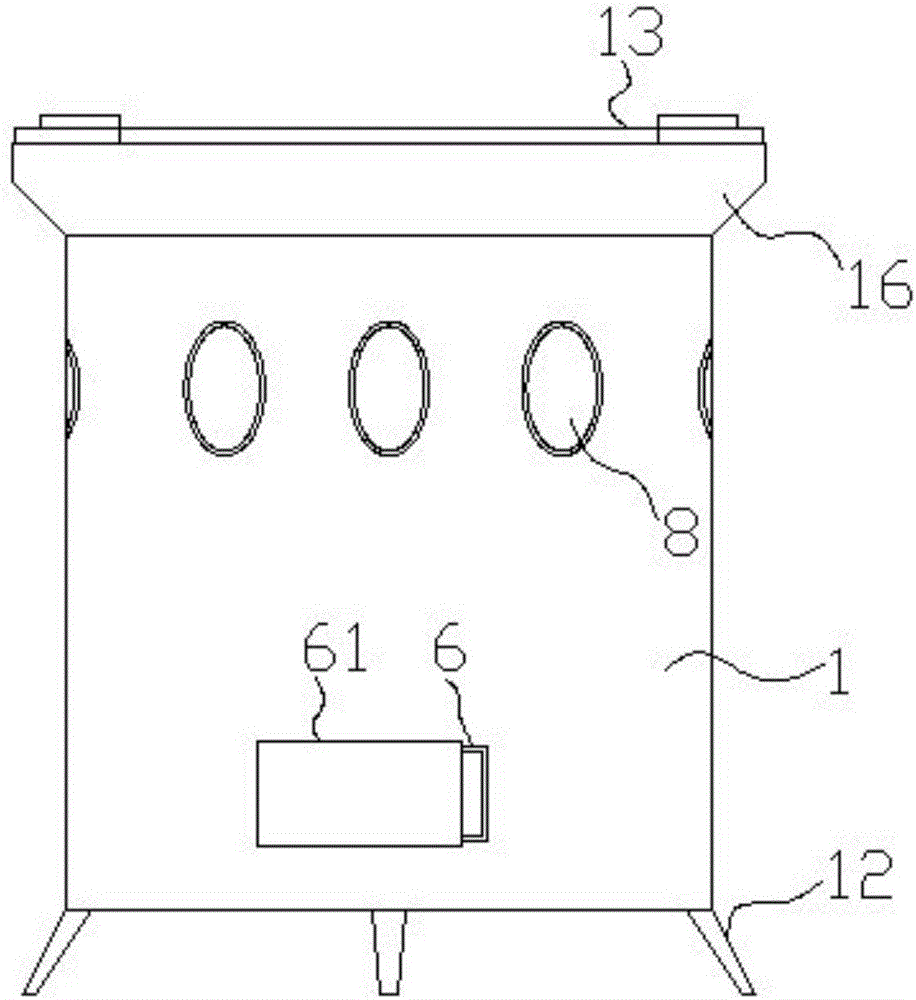
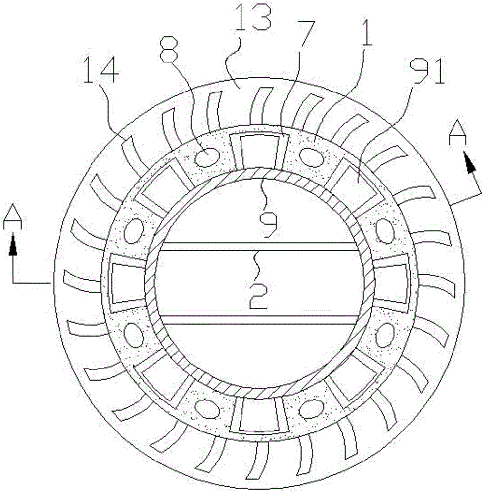
[0029] Such as Figure 1-Figure 7 As shown, the specific structure of the present invention is: a safe and energy-saving oven, which includes a furnace body 1 and a furnace platform 16 at the upper end; There is a chamber 9; the bottom of the chamber 9 is provided with a furnace grate 2; the inner wall of the hollow cavity of the furnace body 1 is evenly provided with a vertical suction groove 7 through up and down; the furnace body 1 is located on two Vents 8 are arranged between each suction groove 7; the outlet of the vents 8 is arranged on the slope 17 of the furnace platform 16, and the entrance ...


PUM


Abstract

The invention discloses a safety and energy-saving combustion furnace. The safety and energy-saving combustion furnace comprises a furnace body and a furnace table arranged at the upper end of the furnace body. Landing legs are arranged at the bottom of the furnace body. A hearth barrel is arranged in a hollow cavity of the furnace body. A grate is arranged at the bottom of the hearth barrel. Vertical vertical-through air suction grooves are evenly formed in the inner wall of the hollow cavity of the furnace body. Exhaust holes are formed in the positions, located between every two adjacent air suction grooves, of the furnace body, exhaust hole outlets are formed in the oblique face of the furnace table, and exhaust hole inlets are formed in the outer wall of the furnace body. Guide vanes are arranged at the positions, located at the top ends in the air suction grooves, of the outer wall of the hearth barrel, and the lower end of the hearth barrel is connected to a bottom hearth base in a sleeved manner. A slag cavity is formed by the bottom hearth base and communicates with air inlet holes. By means of the safety and energy-saving combustion furnace, the combustion time of honeycomb briquette can be controlled, meanwhile, the generating amount of carbon monoxide is greatly reduced, and using is safer and more reliable.

Description

technical field [0001] The invention belongs to the technical field of coal furnace equipment, in particular to a safe and energy-saving oven. Background technique [0002] Coal stove is a stove fueled by coal. Because of its long burning time and quick and convenient use, it is still widely used in rural China, mainly for heating in winter and cooking and boiling water. The structure of the existing domestic coal stove is generally as follows figure 1 As shown, the furnace body 1 is hollow to form a furnace 4, a furnace grate 2 is arranged in the furnace 4, honeycomb briquettes 3 are placed on the furnace grate 2 to burn, and a slag chamber 5 is arranged at the lower end of the furnace grate 2, and the slag chamber 5 is connected to the air inlet 6. There is one biggest disadvantage of this traditional coal stove. When the honeycomb coal is not fully burned, it will produce a large amount of carbon monoxide gas. Causes hypoxia in the body tissue, leading to suffocation an...

Claims


Application Information

Patent Timeline
Patent Type & Authority Applications(China)
IPC IPC(8): F24B1/18F24B1/19F24B1/191
CPCF24B1/18F24B1/19F24B1/191
Inventor 卢永强
Owner 卢永强
Why Eureka
Try Eureka