
Bending composite loader, testing device and system for main shaft of machine tool

A technology of machine tool spindle and composite loading, which is applied in the testing of machine/structural components, measuring devices, and testing of mechanical components, etc. It can solve problems such as inability to simulate loads effectively, and achieve the effect of improving safety and accuracy.

Inactive Publication Date: 2017-05-17
SHENZHEN GRADUATE SCHOOL TSINGHUA UNIV
View PDF5 Cites 4 Cited by
  • Summary
  • Abstract
  • Description
  • Claims
  • Application Information

AI Technical Summary

Problems solved by technology

Whether it is a single torque load or radial force load, or a contact mixed load, it cannot effectively simulate the load under the actual working condition of the machine tool spindle.

Method used


Image

  • Bending composite loader, testing device and system for main shaft of machine tool
  • Bending composite loader, testing device and system for main shaft of machine tool
  • Bending composite loader, testing device and system for main shaft of machine tool

Examples


Embodiment 1

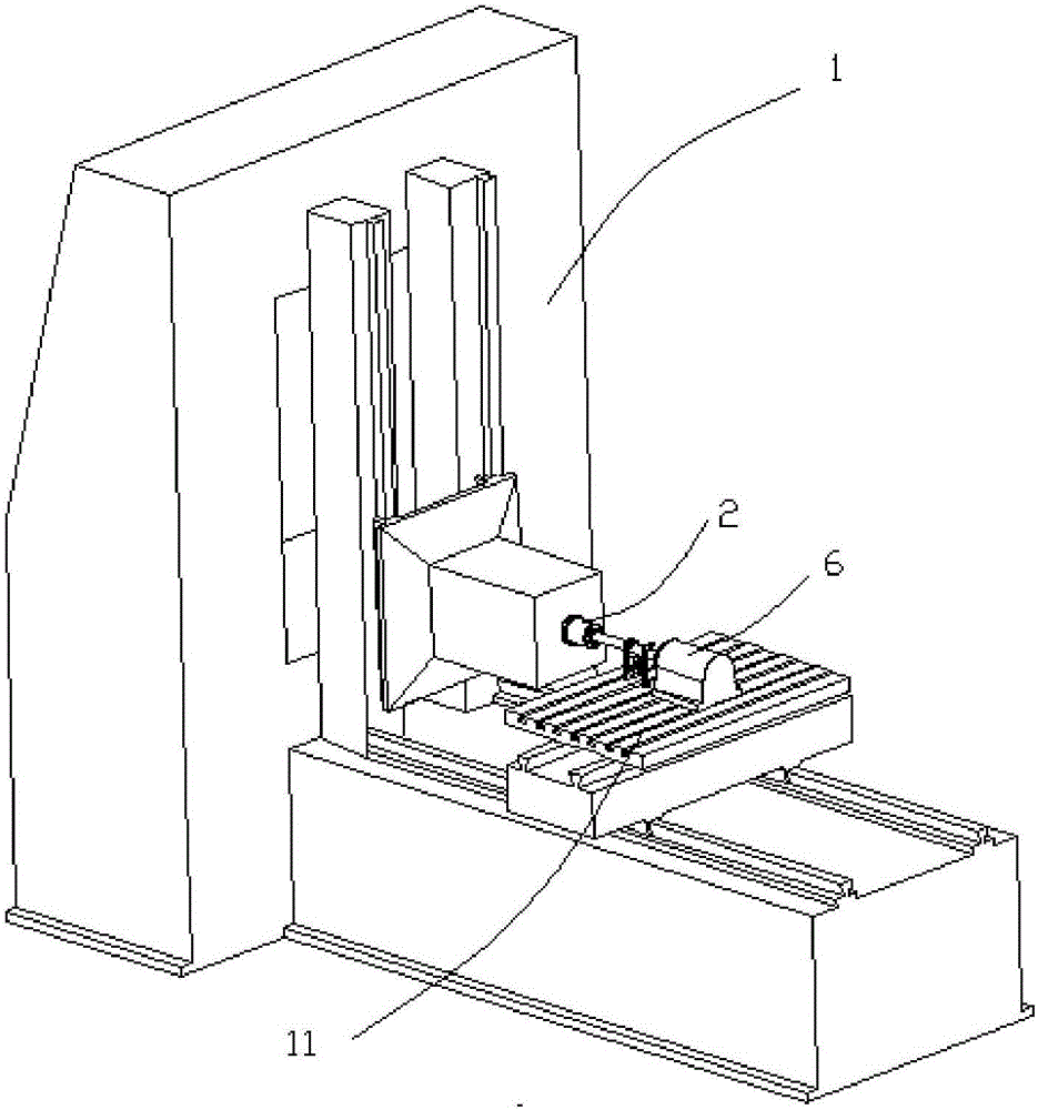
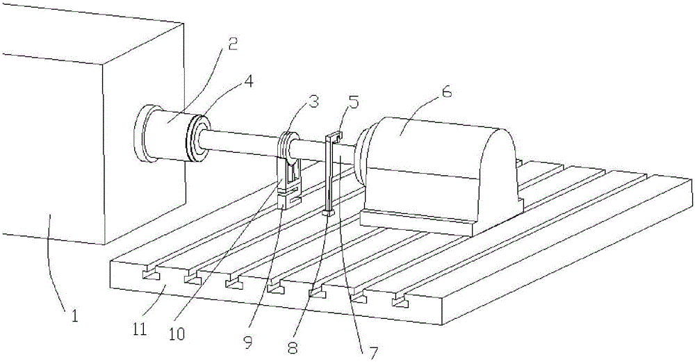
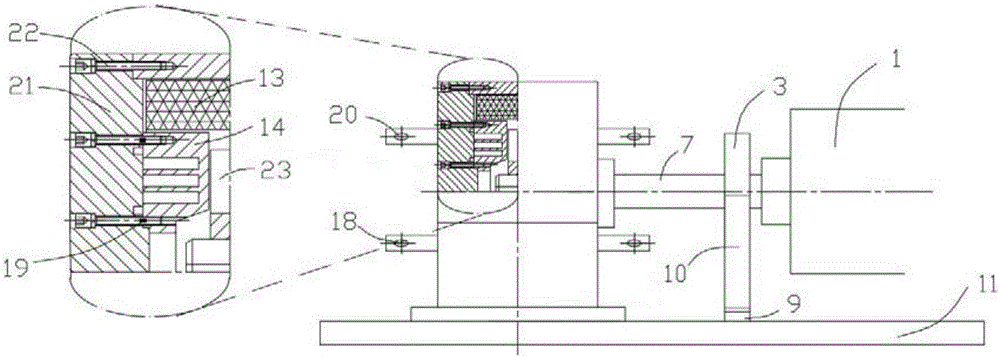
[0028] This embodiment provides a machine tool spindle bending and torsion composite test device, the overall assembly diagram is as figure 1 As shown, the enlarged view is as figure 2 Shown. The testing device is installed on the machine tool workbench 11, including: the machine tool spindle 2, the torque loader 6, the radial loader 10 and the test rod 7. One end of the machine tool spindle 2 is connected to the test rod 7 through the tool holder 4, and the other end is connected to the torque The sensing parts of the loader are connected (not shown in the figure). The radial loader 10 is installed on the radial sensor 9 to realize the radial force loading and the measurement of the radial force on the test rod 7; the radial force enhancement component 3 is also arranged above the radial loader 10, The force-enhancing component 3 and the test rod 7 are interference-connected. The displacement sensor 5 is installed above the test rod 7 through the mounting bracket 8 for measu...

Embodiment 2

[0035] This embodiment provides a machine tool spindle bending and torsion composite test system. The test system includes the machine tool spindle bending and torsion composite test device described in Embodiment 1, and further includes a signal processing device. The signal processing device is connected to a torque sensor (strain gauge), The radial sensor and the displacement sensor are connected to collect three-way signals and input them into the computer for data processing to measure the influence of torque on bending deformation. Among them, before the experiment, the corresponding strain gauge must be calibrated first, and the relationship between the signal size of the strain gauge and the loading force under different loads is given, and then the signal size of the strain gauge during the actual loading process and its radius from the axis Calculate the actual load torque.

[0036] The method for evaluating the influence of torque on bending deformation in the non-cont...


PUM


Abstract

The invention provides a bending composite loader, testing device and system for a main shaft of a machine tool. The composite loader includes a main shaft of a machine tool, a torque loader, a radial loader and a test rod, wherein the torque loader includes a torsional force loading part and a torsional force induction part; the radial loader includes a radial force loading part; one end of the test rod is connected with the main shaft of a machine tool, and the other end of the test rod is connected with the torsional force induction part; the torsional force loading part generates torsional force, and the torsional force is loaded to the test rod through the torsional force induction part in a non-contact mode; and the radial force loading part generates radial force, and the radial force is loaded to the test rod in a non-contact mode. By loading torsional force and radial force to the test rod in a non-contact mode and simulating the practical condition of the main shaft for a machine tool during the operating process, the bending composite loader, testing device and system for a main shaft of a machine tool can avoid influencing the final deflection of the operating main shaft during the contact type force loading process, and can avoid crashing and rubbing the test rod, thus improving the safety of the test.

Description

Technical field [0001] The invention belongs to the field of monitoring the dynamic performance of a numerical control machine tool, and specifically relates to a bending and torsion composite loader, a testing device and a system of the machine tool spindle under the operation of the machine tool. Background technique [0002] CNC machining machine tools are currently developing in the direction of high-speed and high-precision machining, and the imbalance of machine tool spindle parts caused by manufacturing errors, installation misalignment, and part wear is an important reason that affects machining accuracy. The existence of these unbalances causes forced vibration of the machine tool spindle during operation, which interferes with the cutting process of the machine tool. When the unbalance reaches a certain value, it will have a significant impact on the machining accuracy of the machine tool. [0003] During the cutting process, the spindle of the machine tool is subjected t...

Claims


Application Information

Patent Timeline
IPC IPC(8): G01M13/00G01M5/00
CPCG01M5/005G01M13/00
Inventor 许超冯平法周凯吴志军马荣梅
Owner SHENZHEN GRADUATE SCHOOL TSINGHUA UNIV
Learn More