Graphene surface achromatic Airy light beam generator excited by Array grating

A graphene surface and beam generator technology, applied in the optical field, can solve the problems of difficult phase modulation, weak interaction between light and graphene, etc., and achieve the effect of ultra-long beam propagation distance, wide application potential, and strong binding ability.

Active Publication Date: 2017-05-17
HARBIN ENG UNIV
View PDF4 Cites 11 Cited by
  • Summary
  • Abstract
  • Description
  • Claims
  • Application Information

AI Technical Summary

Problems solved by technology

However, the single-layer graphene on the dielectric layer is too thin so that the interaction between light and graphene is too weak, and it is difficult to achieve phase modulation in the range of 2π only by adjusting the Fermi level and width of the graphene band in the transmission mode device.

Method used


Image

  • Graphene surface achromatic Airy light beam generator excited by Array grating
  • Graphene surface achromatic Airy light beam generator excited by Array grating
  • Graphene surface achromatic Airy light beam generator excited by Array grating

Examples


Embodiment 1

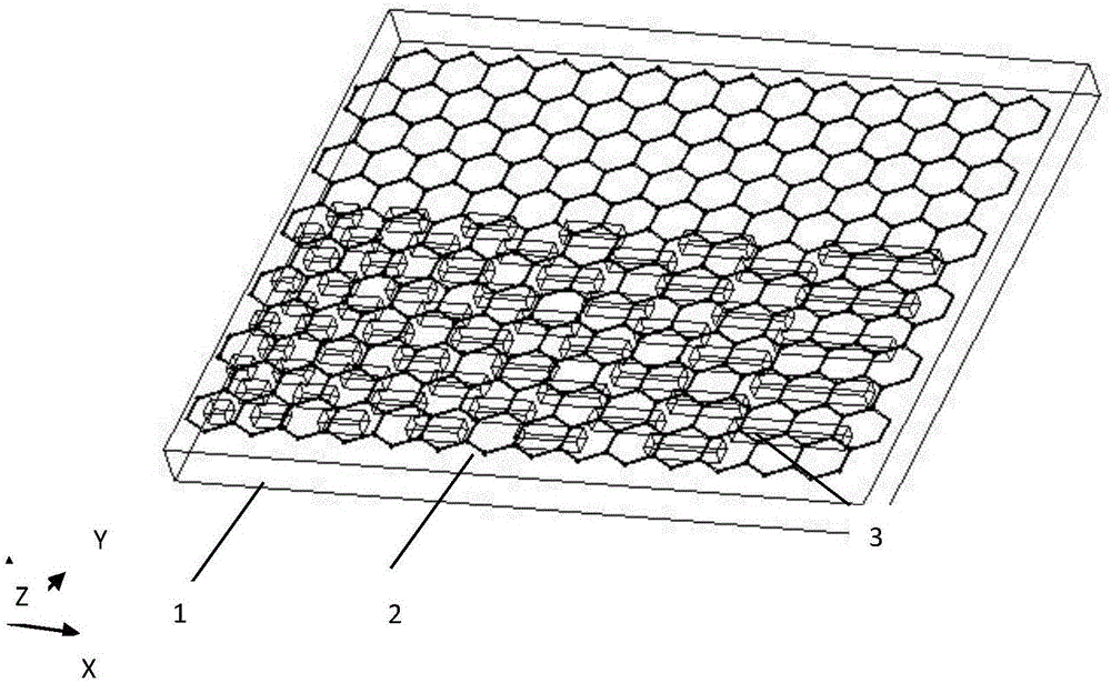
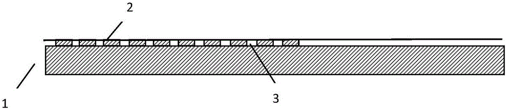
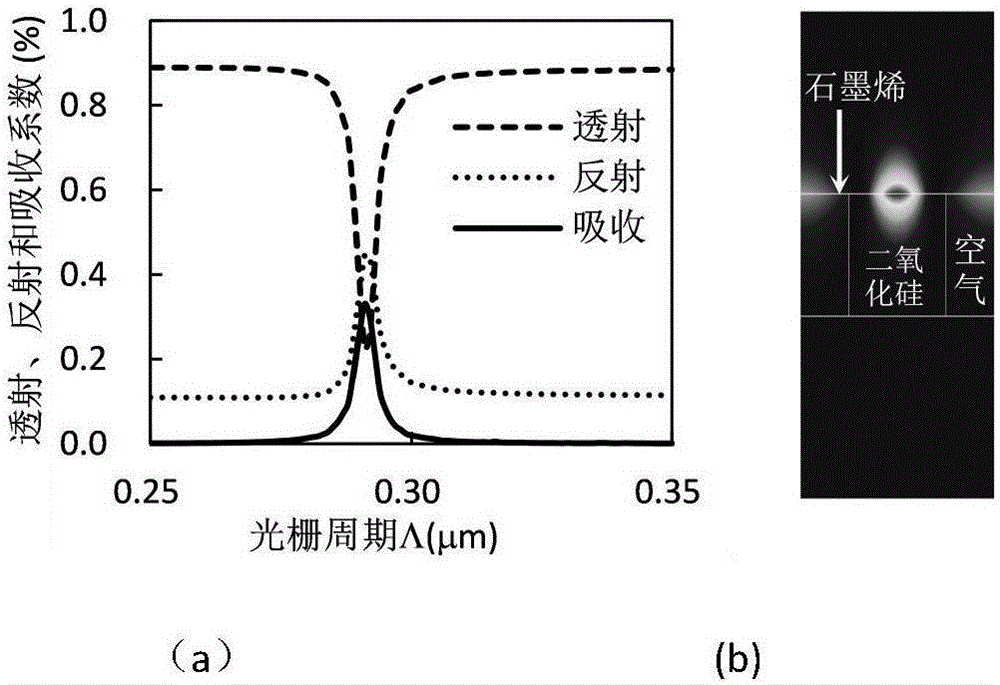
[0033] Graphene Surface Airy Beam Generator ( Figure 1-7 ), Figure 1-2 1 in it is a silicon dioxide or semiconductor substrate, 2 is a graphene film, and 3 is a grating array. Silica grating array height h 0 The thickness of the graphene layer is 100nm, the thickness of the graphene layer is 0.7nm, and the dielectric constant ε of silicon dioxide in the mid-infrared band is 3.9. The Fermi level is 0.65eV. When the grating period gradually increases from 0.25 to 0.35, the function curves of transmission coefficient (T), reflection coefficient (R) and absorption coefficient (A) are shown in image 3 (a). When the grating period is about 290nm, the maximum absorption coefficient of graphene plasmon waves can reach 33%. Under the maximum excitation efficiency, the electric field energy distribution of a single grating element in the x-z plane (|E x | 2 )See image 3 (b), The figure shows the graphene surface plasmon wavefield with locally enhanced amplification. The pro...

Embodiment 2

[0037] like Figure 10-12 shows that, unlike Example 1, Figure 10-11 It is the complementary structure of the Airy beam generator on the graphene surface, and the generated Airy beam propagates at the interface between the graphene and the substrate. Under the same incident light frequency of 34.88THz, the wavelength of the plasmon wave generated between the graphene dielectric interface is only 230nm, the half width of the main wave packet of the Airy beam is 350nm, and the electric field distribution on the graphene surface is shown in Figure 12. The grating array has a period of 275nm and a duty cycle of 0.3. The main lobe deflects 0.7 μm in the y direction at 8.5 μm from the end of the grating, and the half-width of the main wave packet is 780 nm at a transmission distance of 1 μm from the end of the grating. Similarly, this structure can also realize the dispersion characteristic.

[0038] The invention provides a graphene surface dedispersion Airy beam generator exci...


PUM


Abstract

The invention belongs to the technical field of optics, and in particular to a graphene surface achromatic Airy light beam generator excited by Array grating in the field of special light beam generation apparatuses and optical trapping. According to the invention, the light beam generator is composed of a silicon dioxide or a semiconductor material which serves as a substrate, a nano diffraction grating array structure which is inscribed in the surface of the substrate, and a single-layer graphene which is laid on the surface of the grating. The Airy light beam generator has strong mode restraining capability, has ultra-long light beam propagating distance, and has important significance in micro-optical particle manipulation and optical shaping; since the tenability and flexibility of materials of the graphene, the apparatus can provide dynamic tuning properties, and is easy to operate; the generator can work in medium infrared wave band and Terahertz wave band, and the SPP of the Terahertz wave band happens to be at sensitive wave band of an organism. Therefore, the apparatus has wide application potential in the field of biosensing.

Description

technical field [0001] The invention belongs to the field of optical technology, in particular to a graphene surface dedispersive Airy beam generator used for array grating excitation in the field of special beam generating devices and optical trapping. Background technique [0002] The beam shaping and manipulation technology based on the modulation of light wave amplitude and phase is a hot research topic at present. It provides many beams with unique field distribution, and plays an important role in the fields of optical micro-manipulation and optical micro-trapping, micro-optics and optical communication. effect. Most beam shaping techniques rely on linear optics and therefore only work at a single wavelength or with fixed parameters that cannot be adjusted externally. Graphene, a material made of a single layer of carbon atoms, has become a popular choice for light-tunable devices, especially at infrared and terahertz wavelengths. The mechanical, electronic, and opti...

Claims


Application Information

Patent Timeline
Patent Type & Authority Applications(China)
IPC IPC(8): G02B5/00G02B5/18
CPCG02B5/008G02B5/1819G02B5/1857
Inventor 关春颖王猛黄鹏陆永娇朱正史金辉苑立波
Owner HARBIN ENG UNIV
Why Eureka
Try Eureka