Closure device
A technology of occluder and occlusion disc, which is applied in the fields of medical science, surgery, ligation, etc., can solve problems such as the inability to achieve film covering, and achieve the effects of improving anatomical adaptability, reducing body shape, and making it convenient
- Summary
- Abstract
- Description
- Claims
- Application Information
AI Technical Summary
Problems solved by technology
Method used
Image
Examples
Embodiment 1
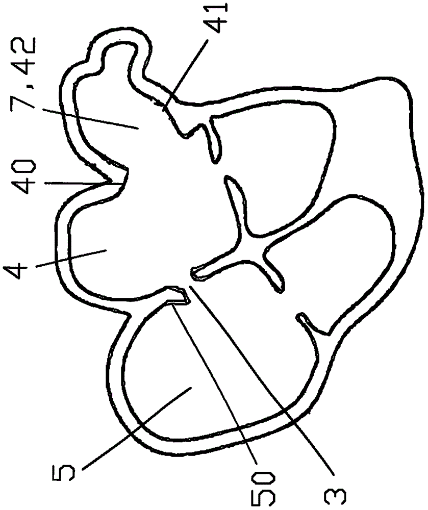
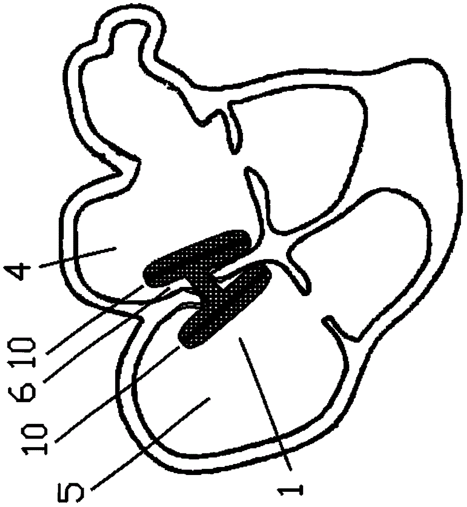
[0051] The occluder of the first embodiment of the present invention can be used for the closure of defect openings, such as atrial septal defect, ventricular septal defect, and tissue breaches such as blood vessels.
[0052] like Figures 5a-5b ,as well as Figures 6a-6c As shown, the occluder includes two occlusion disks 10, wherein any occlusion disk 10 includes two central ends 100 and 100', two occlusion surfaces 101 and 101', and one of the occlusion surfaces 101 consists of A plurality of main rods 1010 that directly diverge from the central end 100 to the edge of the blocking surface are formed, and another blocking surface 101' is connected to the blocking surface 101 through a connecting rod 103, and the connecting rod 103 is formed from each of the main rods. The rod 1010 is composed of two or more sub-rods 1011, and the two or more sub-rods 1011 are respectively combined with the sub-rods 1011 of the adjacent main rod 1010 to form another main rod 1010' of the sea...
Embodiment 2
[0061] like Figure 7a-7b As shown, based on the first embodiment, the difference between the second embodiment and the first embodiment is that the sealing surface 101 of any blocking disk 10, the multiple sub-rods 1011 of the main rod 1010 are substantially parallel to each other, and the main rod 1010 penetrates the membrane 102 . This design further fixes the relative position of the membrane 102 and the main rod 1010. After the occlusion surface 101 is compressed and enters the delivery sheath, the membranes are arranged in an orderly manner in the sheath to achieve tight filling instead of the chaos of the membranes of traditional occluders. Disorder leads to larger gaps. Because this design reduces the size of the occlusion surface 101 of the occlusion disk 10 after compression, it reduces the minimum diameter of the delivery sheath used, reduces the requirements for the surgical approach, and expands the space. The scope of application of the occluder. The multiple s...
Embodiment 3
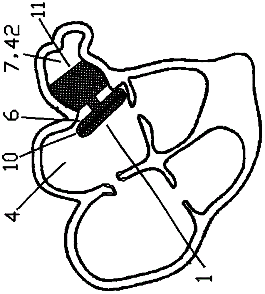
[0063] The occluder of the third embodiment of the present invention can be used for occlusion of lumens and organ passages, such as patent ductus arteriosus and left atrial appendage.
[0064] like Figures 8a-8b As shown, based on the first embodiment, the third embodiment differs from the first embodiment in that the occluder includes an occlusion disk 10 and an anchor frame 11 . The anchoring frame 11 is placed inside the lumen or organ channel, and plays the role of fixing the occluder. The main rod 1010 of the plugging surface 101 is provided with a thread hole 1014, or the gap between the sub-rods 1011 with intertwined weaving structure is used to form a thread hole, and the series thread 1013 passes through the thread hole 1014 to make multiple main rods 1010 connected in series. like Figure 8a As shown, and a sealing surface 101 is wrapped inside the membrane 102, such as Figure 8b As shown, this design makes the film 102 on both sides of the plugging surface 101...
PUM
 Abstract
Description
Claims
Application Information
 - R&D
- Intellectual Property
- Life Sciences
- Materials
- Tech Scout
- Unparalleled Data Quality
- Higher Quality Content
- 60% Fewer Hallucinations
Browse by: Latest US Patents, China's latest patents, Technical Efficacy Thesaurus, Application Domain, Technology Topic, Popular Technical Reports.
© 2025 PatSnap. All rights reserved.Legal|Privacy policy|Modern Slavery Act Transparency Statement|Sitemap|About US| Contact US: help@patsnap.com


