Liquid phase hydrogenation reactor and liquid phase hydrogenation process

A liquid-phase hydrogenation and reactor technology, which is used in hydrotreating processes, chemical instruments and methods, and petroleum industry, etc., can solve the problems of reduced reaction efficiency, inability to effectively handle sulfur, and no disclosure of reactor structure, etc. Impurity removal rate, improving utilization efficiency and catalyst service life, and the effect of effectively removing impurities

Active Publication Date: 2017-05-24
KYMSON LUOYANG PETROCHEM EQUIP
View PDF7 Cites 2 Cited by
  • Summary
  • Abstract
  • Description
  • Claims
  • Application Information

AI Technical Summary

Problems solved by technology

But it does not completely solve the H that will be produced during the hydrofining reaction 2 S, NH 3 The problem of removal of harmful impurities such as sulfide and other harmful impurities leads to their continuous accumulation in the reactor, which greatly reduces the reaction efficiency and cannot effectively handle raw materials with high sulfur and nitrogen content. The above-mentioned documents do not disclose the specific structure of the reactor

Method used


Image

  • Liquid phase hydrogenation reactor and liquid phase hydrogenation process
  • Liquid phase hydrogenation reactor and liquid phase hydrogenation process
  • Liquid phase hydrogenation reactor and liquid phase hydrogenation process

Examples


Embodiment 1-4

[0076] The present invention proposes a liquid-phase hydrogenation reactor and a liquid-phase hydrogenation process. The properties of the raw material oil used are shown in Table 1. The catalyst is selected from the existing industrial FH-UDS hydrogenation catalyst. The hydrogenation process conditions are shown in Table 2. The properties of the generated oil are shown in Table 3 (the data obtained by sampling and analysis of the device running for 300 hours).

[0077] Table 1 Properties of raw oil

[0078] project Raw oil 1 Raw oil 2 Density(20℃) / (g / cm 3 )

0.8723 0.8654 Distillation range / ℃ 132-365 168-370 Sulfur content / (μg / g) 8201 11758 Nitrogen content / (μg / g) 652 1002 Actual colloid / (mg / 100ml) 274 780 Polycyclic aromatic hydrocarbons / m% 17.2 14.4 Total aromatics / m% 32.8 28.8 cetane number 42.5 47.4

[0079] Table 2 Hydrogenation process conditions

[0080]

[0081]

[0082] Table 3 Properti...


PUM


Abstract

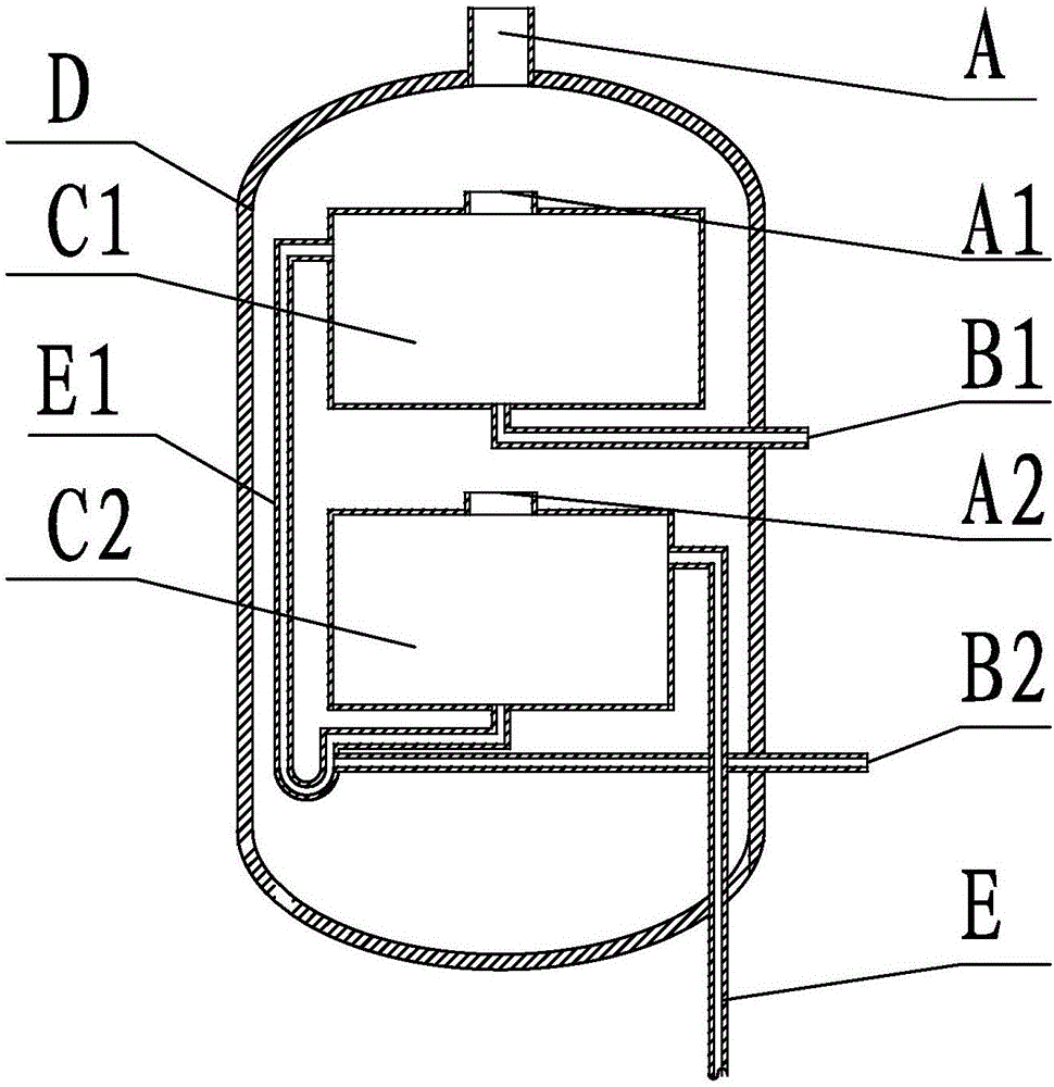
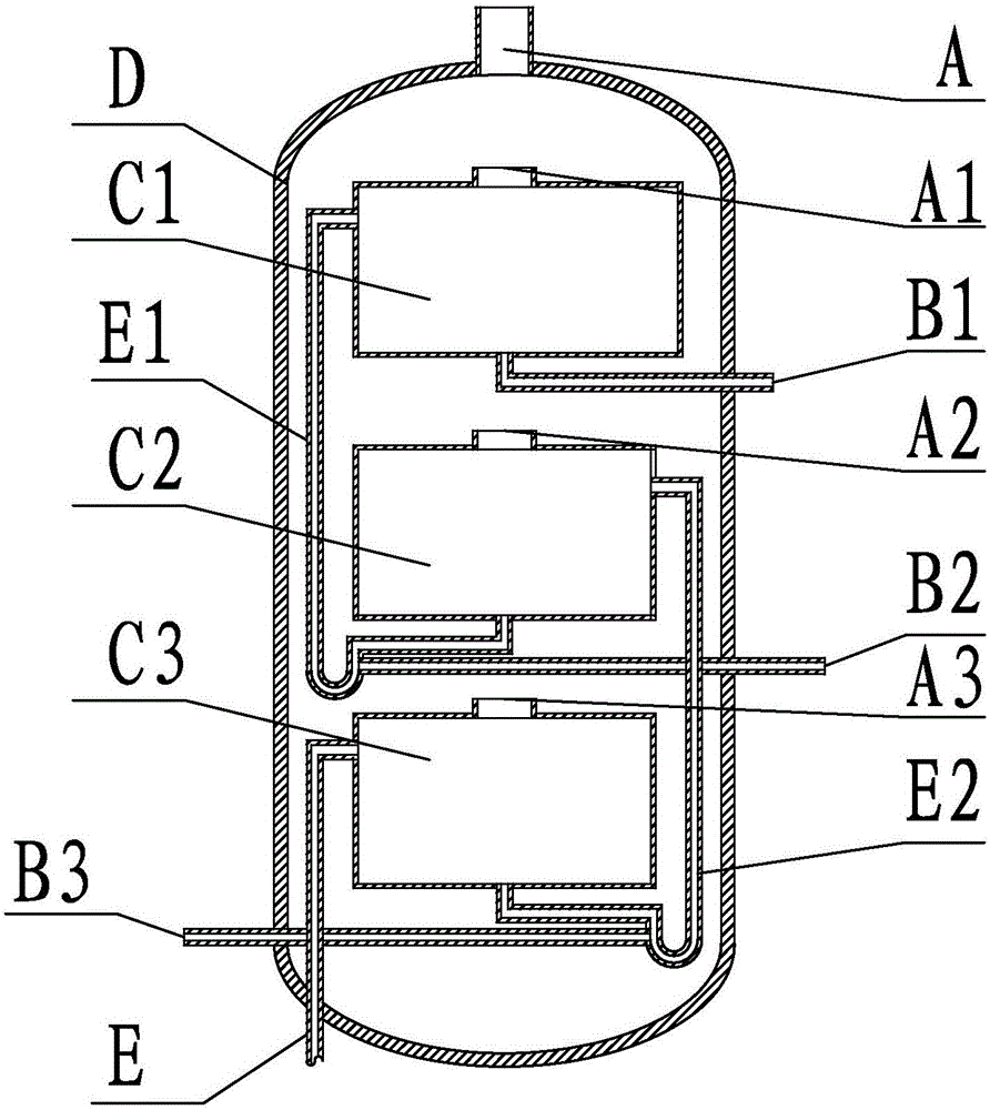
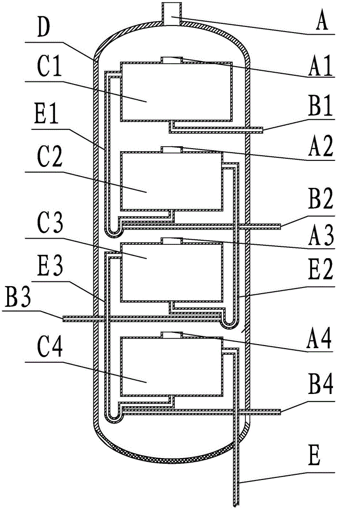
The invention relates to a liquid phase hydrogenation reactor and a liquid phase hydrogenation process. The liquid phase hydrogenation reactor comprises a total exhaust gas discharging opening A, independent catalyst bed exhaust gas discharging openings A1-An, a raw oil inlet pipeline B1, hydrogen supplementing pipelines B2-Bn, a plurality of independent catalyst beds C1-Cn, a reactor barrel D, a product outlet pipeline E and liquid phase product conveying pipelines E1-E(n-1), wherein n is an integer greater than 1. The plurality of independent catalyst beds are serially connected inside the reactor, and the exhaust gas discharging opening is formed in the top of each catalyst bed, so that an adverse impact of H2S, NH3 and other harmful impurities produced in the reaction on the hydrogenation reaction can be avoided; the new hydrogen supplementing opening is formed at the feed opening of each catalyst bed so as to ensure that a liquid raw material can sufficiently dissolve hydrogen. In addition, through arrangement of the independent catalyst beds, compatibility of catalysts can be performed according to different raw oil properties, so that the hydrogenation efficiency is improved, and the service life of the catalysts is prolonged.

Description

technical field [0001] The invention relates to a liquid-phase hydrogenation reactor and a process method, in particular to a liquid-phase hydrogenation reactor for hydrogenation to generate oil circulation, and a liquid-phase hydrogenation process using the reactor. Background technique [0002] In the conventional fixed-bed hydrogenation process, in order to remove impurities such as sulfur, nitrogen, oxygen, and metals in the raw material or reduce the size of the raw oil molecule, catalytic hydrogenation reaction is required. In order to control the reaction temperature of the catalyst bed and avoid catalyst deactivation due to carbon deposition, a larger hydrogen-to-oil volume ratio is usually used, and there must be a large amount of hydrogen surplus after the hydrogenation reaction is completed. The excess hydrogen is usually pressurized by the circulating hydrogen compressor and then mixed with new hydrogen to continue as the hydrogen feed for the reaction. In this ...

Claims


Application Information

Patent Timeline
Patent Type & Authority Applications(China)
IPC IPC(8): B01J8/04C10G65/02
Inventor 范合松
Owner KYMSON LUOYANG PETROCHEM EQUIP
Why Eureka
Try Eureka