Electromagnetic forming device and method of metal pipe

A metal pipe fitting and electromagnetic forming technology, applied in the field of metal pipe fitting forming, can solve the problems of limited coil energy, pipe bulging, huge investment, etc., and achieve the effects of reducing discharge voltage, improving service life, and simplifying structural design.

Active Publication Date: 2017-05-24
HUAZHONG UNIV OF SCI & TECH
View PDF10 Cites 23 Cited by
  • Summary
  • Abstract
  • Description
  • Claims
  • Application Information

AI Technical Summary

Problems solved by technology

However, the main problems existing in the existing electromagnetic forming methods for metal pipe fittings are: (1) The maximum capacity of the current electromagnetic forming power supply is generally less than about 500kJ, and the voltage resistance of the thyristors used is generally 25kV, and can withstand tens of thousands of amperes for long-term use. , if the forming ability is to be further improved, a power source with greater energy and a switching device with better performance will be required, which will cost a huge investment and be difficult to implement. Therefore, electromagnetic forming is currently only suitable for materials with good electrical conductivity and low mechanical strength. Metal (such as copper, aluminum alloy), and the wall thickness of metal pipe fittings is generally less than 3mm; (2) The position of the coil and the pipe fitting is relatively fixed. (3) For pipe bulging, the forming coil must be placed in the metal pipe in the traditional method, and an eddy current is induced in the metal pipe by passing a pulsed strong current into the coil, and the eddy current and the coil current The generated magnetic field interacts to form a radially outward electromagnetic force, so as to achieve the purpose of bulging of metal pipe fittings, which belongs to the electromagnetic forming of metal pipe fittings based on electromagnetic repulsion force
However, when the inner diameter of the pipe is small, if the traditional electromagnetic forming method is used to bulge the pipe, if multiple sub-coils are used for winding, the diameter of the eddy current coil will be very small, resulting in difficulty in coil winding; and if one sub-coil is used As an eddy current coil, it is difficult to bulge the pipe due to the limited energy that the coil can withstand

Method used


Image

  • Electromagnetic forming device and method of metal pipe
  • Electromagnetic forming device and method of metal pipe
  • Electromagnetic forming device and method of metal pipe

Examples


no. 1 example

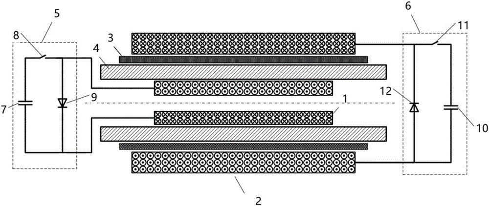
[0030] figure 1 It is the first embodiment of the electromagnetic forming device for metal pipe fittings provided by the present invention. The electromagnetic forming device is used for electromagnetic forming of composite pipes, and the composite pipes are composed of metal pipe fittings 4 and forming dies 3 . The metal pipe fitting 4 is a copper-nickel alloy seamless pipe, which has poor conductivity and shape. The inner diameter of the metal pipe fitting is 46.6mm and the wall thickness is 4.2mm. The forming die 3 is a seamless steel pipe, the inner diameter of the forming die is 57.8 mm, and the wall thickness is 2.6 mm. The forming die 3 is set on the outside of the metal pipe fitting 4. The forming die 3 is used to constrain the shape of the metal pipe fitting 4 during the forming process. Finally, the metal pipe fitting 4 and the forming die 3 are closely attached to form a composite pipe. The outer surface of the composite pipe is a steel pipe. , the inner surface of...

no. 2 example

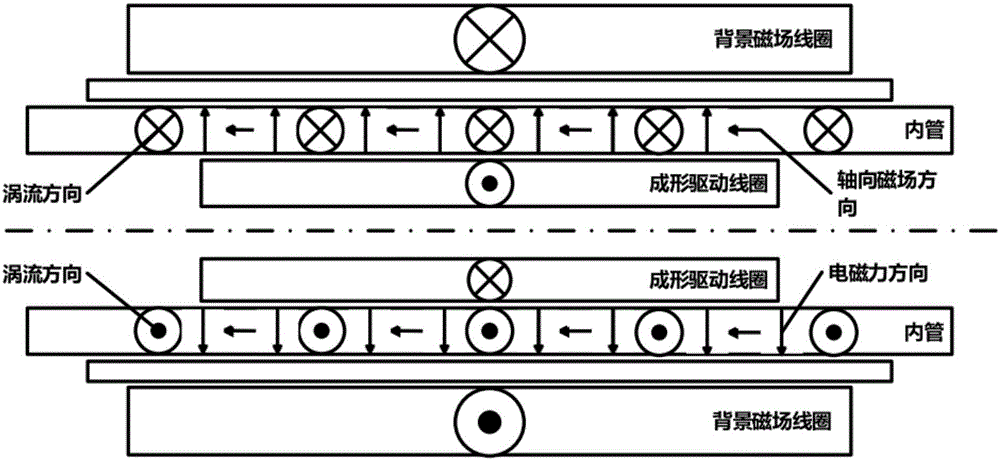
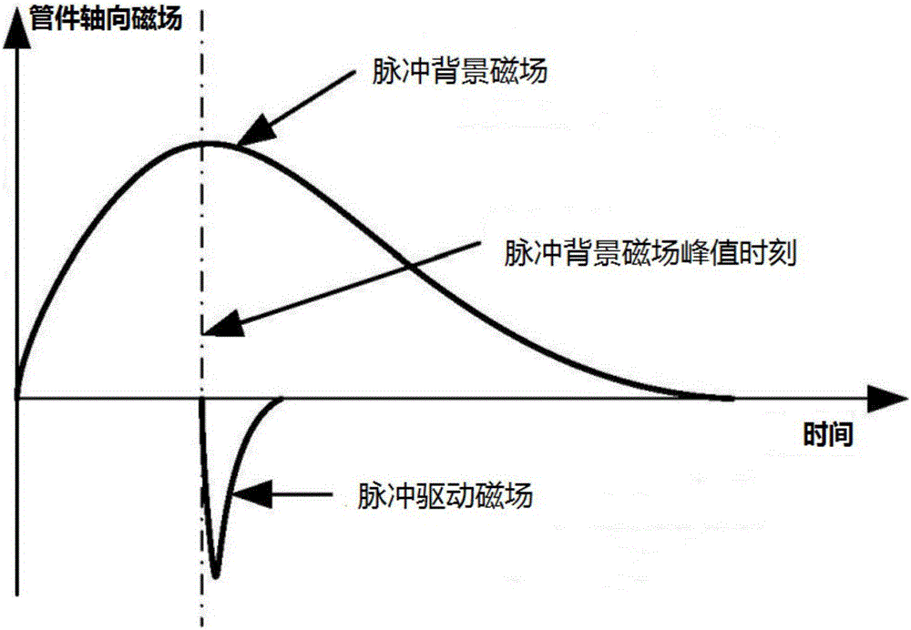
[0038] Figure 4 It is the second embodiment of the electromagnetic forming device for metal pipes provided by the present invention. The electromagnetic forming device is used to process the metal pipe 4 to the shape of the inner cavity of the forming mold 3 , and the metal pipe 4 is located inside the forming mold 3 . The electromagnetic forming device includes a background magnetic field coil 2 and a forming drive coil 1. Both the forming drive coil 1 and the background magnetic field coil 2 are in the shape of a hollow column, the background magnetic field coil 2 is set outside the forming drive coil 1, and the forming drive coil 1 is set on the forming mold 3 The outside is fixed by the upper and lower end clamps 13, so that the metal pipe 4, the forming mold 3, the forming driving coil 1 and the background magnetic field coil 2 are coaxial. The first pulse current whose pulse period is less than 1ms is passed into the forming drive coil 1, the second pulse current whose ...


PUM


Abstract

The invention discloses an electromagnetic forming device and method of a metal pipe. The device comprises a background magnetic field unit and a metal pipe forming driving coil, wherein the background magnetic field unit is used for generating a pulse background magnetic field on the metal pipe, and a pulse driving magnetic field can generate vortexes on the metal pipe; and the metal pipe forming driving coil is used for generating the pulse driving magnetic field on the metal pipe. Due to the fact that the pulse width of the pulse driving magnetic field is much smaller than that of the pulse background magnetic field, the vortexes generated by the pulse background magnetic field on the metal pipe can be ignored, meanwhile, the influences of the pulse driving magnetic field on a magnetic field on the metal pipe can be ignored, and thus, electromagnetic force is generated on the metal pipe through interaction of the pulse background magnetic field and the vortexes. By independently adjusting the pulse background magnetic field and the pulse driving magnetic field, the electromagnetic force can be improved, the metal pipe high in mechanical strength and low in conductivity can be formed, meanwhile, the design difficulty of the forming driving coil can be lowered, and the service life of the forming driving coil is prolonged.

Description

technical field [0001] The invention belongs to the field of forming metal pipe fittings, and more specifically relates to an electromagnetic forming device and method for metal pipe fittings. Background technique [0002] Electromagnetic forming is a high-energy, high-speed special processing method for plastically processing metal blanks using pulsed electromagnetic force. High process flexibility and flexibility, high processing precision, small residual stress and springback, easy to realize energy control and production automation. Compared with the conventional forming method, the electromagnetic forming technology has the following main advantages: 1. The mold is simple and the production cost is reduced; 2. The precision of the parts is high and the surface quality is good; 3. The plastic deformation ability of the material can be improved and the forming limit can be increased. Therefore, electromagnetic forming has been used in the processing and forming of many t...

Claims


Application Information

Patent Timeline
Patent Type & Authority Applications(China)
IPC IPC(8): B21D26/14
CPCB21D26/14
Inventor 李亮蔡宏曹全梁韩小涛张骁肖涵琛李潇翔
Owner HUAZHONG UNIV OF SCI & TECH
Why Eureka
Try Eureka