
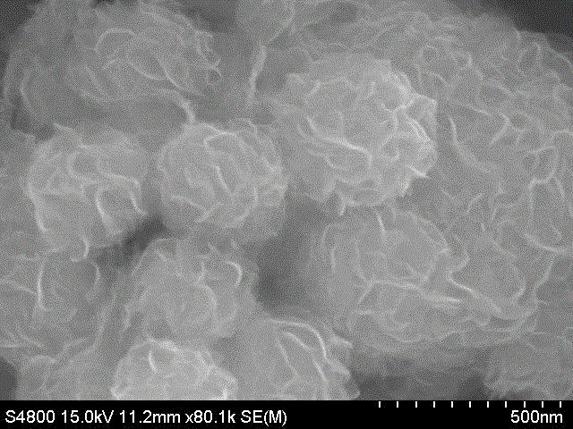
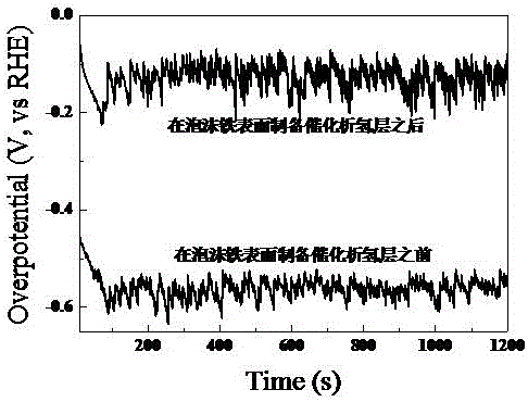
Method for preparing molybdenum disulfide/copper/cobalt catalyzing hydrogen evolution layer on surface of foam iron

A technology of molybdenum disulfide and iron foam, which is applied in the field of preparation of catalytic hydrogen evolution materials, can solve the problem of low hydrogen evolution activity and achieve the effects of large surface area, excellent catalytic activity and increased conductivity

Inactive Publication Date: 2017-05-24
UNIV OF JINAN
View PDF6 Cites 7 Cited by
  • Summary
  • Abstract
  • Description
  • Claims
  • Application Information

AI Technical Summary

Problems solved by technology

[0005] The present invention aims to solve the problem of relatively low hydrogen evolution activity of non-noble metal hydrogen evolution catalysts in acidic solutions, and provides a method for preparing molybdenum disulfide / copper / cobalt catalytic hydrogen evolution layer on the surface of foam iron

Method used


Image

  • Method for preparing molybdenum disulfide/copper/cobalt catalyzing hydrogen evolution layer on surface of foam iron
  • Method for preparing molybdenum disulfide/copper/cobalt catalyzing hydrogen evolution layer on surface of foam iron

Examples


specific Embodiment approach 1

[0017] Specific embodiment one: a kind of method of preparing molybdenum disulfide / copper / cobalt catalytic hydrogen evolution layer on the foam iron surface of the present embodiment is carried out according to the following steps:

[0018] (1) Preparation of flower-like molybdenum disulfide colloidal liquid: a. Weigh 0.5~5.0 g of anionic surfactant, add it into 1000 mL deionized water, stir at room temperature for 5~15 min, then add 0.2~1.2 g flower-shaped molybdenum disulfide; b. After stirring at 60 °C for 2 h, use an ultrasonic cell pulverizer for 2 h; c. repeat step b 1 to 6 times to complete the preparation of flower-shaped molybdenum disulfide colloid;

[0019] (2) Preparation of cationic polyacrylamide gel: d. Dissolve cationic polyacrylamide with a concentration of 3.0-6.0 g / L in deionized water, stir at 40-60 °C for 3-5 h to prepare Cationic polyacrylamide solution;

[0020] (3) Foam iron pre-treatment: e. Soak the foam iron in acetone for 1-5 minutes to remove surf...

specific Embodiment approach 2

[0025] Specific embodiment two: what this embodiment is different from specific embodiment one is that the anionic surfactant described in the a of step (1) is sodium lauryl sulfate, sodium lauryl sulfonate or dodecane One of the base alcohol polyoxyethylene ether sodium sulfates. Others are the same as in the first embodiment.

specific Embodiment approach 3

[0026] Embodiment 3: The difference between this embodiment and Embodiment 1 or 2 is that the molecular weight of the cationic polyacrylamide described in step (2) d is 18 million to 25 million. Others are the same as in the first or second embodiment.


PUM


Abstract

The invention discloses a method for preparing a molybdenum disulfide / copper / cobalt catalyzing hydrogen evolution layer on the surface of foam iron, and relates to a method for preparing a flower-like molybdenum disulfide self-assembly layer / electrocoppering layer / replacement cobalt plating layer with good hydrogen evolution activity on the surface of the foam iron to solve the problem that the hydrogen evolution activity of an existing base metal hydrogen evolution catalyst is relatively low in an acid solution. The method for preparing the molybdenum disulfide / copper / cobalt catalyzing hydrogen evolution layer on the surface of the foam iron comprises the first step of preparation of flower-like molybdenum disulfide colloidal fluid, the second step of preparation of cationic polyacrylamide gel, the third step of pretreatment of the foam iron, the fourth step of self-assembly of flower-like molybdenum disulfide on the surface of the foam iron, the fifth step of electrocoppering and the sixth step of replacement cobalt plating, and the complex coating with good catalyzing hydrogen evolution performance is obtained on the surface of the foam iron. The method for preparing the molybdenum disulfide / copper / cobalt catalyzing hydrogen evolution layer on the surface of the foam iron can improve the capacity of electrolytic hydrogen production and reduce the energy loss.

Description

technical field [0001] The invention belongs to the field of preparation of catalytic hydrogen evolution materials, and relates to a method for preparing a molybdenum disulfide / copper / cobalt catalytic hydrogen evolution layer on the surface of foam iron. Background technique [0002] In today's society where energy is increasingly depleted, how to develop and utilize new renewable energy to replace fossil energy has become one of the most important topics in the world. Under the new energy situation, the use of renewable energy such as solar energy and wind energy to generate electricity has been widely studied. However, due to the non-storage of electrical energy, the electrical energy converted from solar energy, wind energy and other energy sources cannot be stored unless it is consumed. If the electric energy generated by other energy forms is converted into clean energy—hydrogen, the problems of energy regeneration and energy fixation can be well solved. Therefore, ele...

Claims


Application Information

Patent Timeline
IPC IPC(8): C25B11/06C25B11/03C25B1/02
CPCC25B1/02C25B11/031C25B11/091
Inventor 田栋周长利夏方诠花小霞乔雪莹陈培培
Owner UNIV OF JINAN
Learn More