
An engineering drilling rig for automatically loading and unloading drill pipes

An engineering drilling rig, automatic loading and unloading technology, applied in the direction of drill pipe, drilling automatic control system, drill pipe, etc., can solve the problems of unsuitable construction environment, occupying construction channel space, etc., and achieves small space occupation, high connection strength, and reliability. strong effect

Active Publication Date: 2019-01-08
LIAONING HANSHI MACHINERY MFG CO LTD
View PDF6 Cites 1 Cited by
  • Summary
  • Abstract
  • Description
  • Claims
  • Application Information

AI Technical Summary

Problems solved by technology

[0006] Therefore, the technical problem to be solved by the present invention is to overcome that the engineering drilling rig in the prior art needs to be provided with a slide table and hoisting equipment on the side of the drill rig, and the drill pipe angle phase adjustment mechanism and the drill pipe conveying mechanism are arranged on the slide table, which needs to occupy a large amount of time. The construction channel space cannot be applied to the construction environment with less space, so an engineering drilling rig for automatically loading and unloading drill pipes is provided, and the engineering drilling rig includes:

Method used


Image

  • An engineering drilling rig for automatically loading and unloading drill pipes
  • An engineering drilling rig for automatically loading and unloading drill pipes
  • An engineering drilling rig for automatically loading and unloading drill pipes

Examples


Embodiment 1

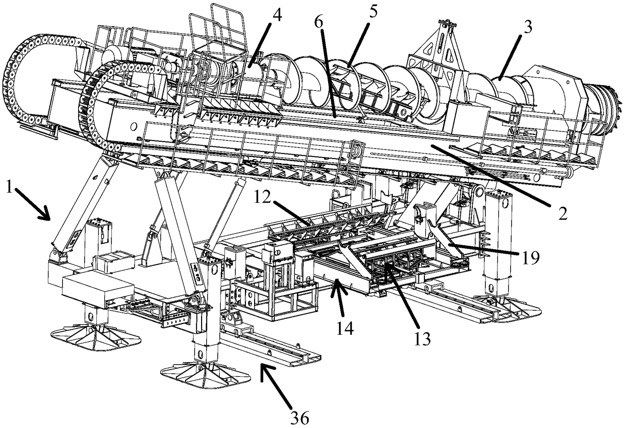
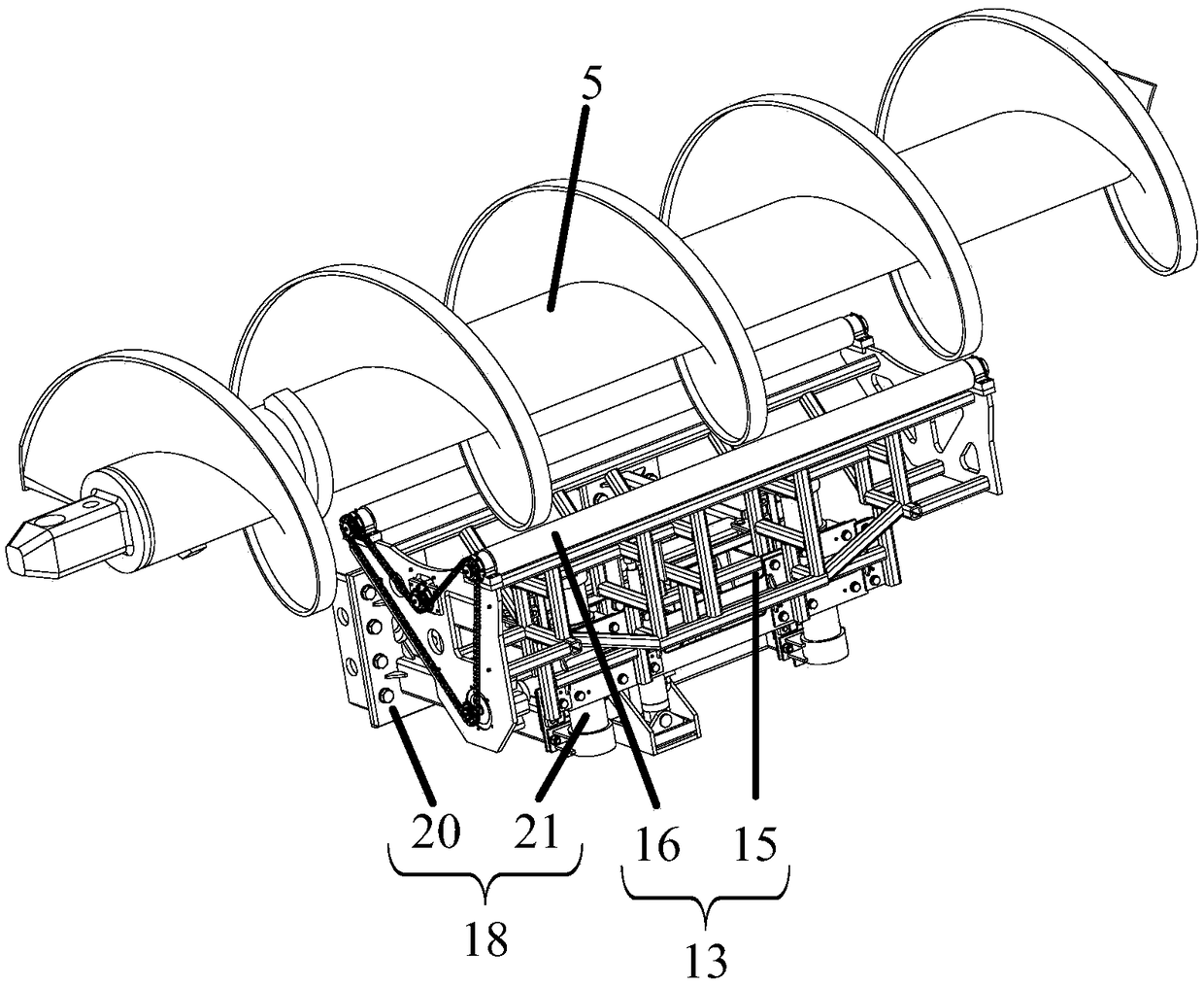
[0055] Independent claim 1 records an engineering drilling rig for automatically loading and unloading drill pipes, such as figure 1 and image 3 As shown, the engineering rig includes:

[0056] Rig body 1,

[0057] The drilling rig platform 2 is arranged on the drilling rig frame body 1 for placing the drill pipe 3 to be loaded and unloaded and the thruster 4, and the drilling rig platform corresponding to the position between the drill pipe 3 to be loaded and unloaded and the thruster 4 for placing the drill pipe 5 for loading and unloading 2 is provided with a loading and unloading drill pipe transfer channel 6;

[0058] The drill pipe angle and phase adjustment mechanism 13 is arranged at the bottom of the drilling rig platform 2, and is used to adjust the circumferential angle of the loading and unloading drill pipe 5 placed thereon;

[0059] The drill pipe horizontal transfer mechanism 14 is arranged at the bottom of the drilling rig platform 2, and is used to receiv...

Embodiment 2

[0090] An engineering drilling rig for automatically loading and unloading drill pipes, such as figure 1 and image 3 As shown, the engineering rig includes:

[0091] Rig body 1,

[0092] The drilling rig platform 2 is arranged on the drilling rig frame body 1 for placing the drill pipe 3 to be loaded and unloaded and the thruster 4, and the drilling rig platform corresponding to the position between the drill pipe 3 to be loaded and unloaded and the thruster 4 for placing the drill pipe 5 for loading and unloading 2 is provided with a loading and unloading drill pipe transfer channel 6;

[0093] The drill pipe angle and phase adjustment mechanism 13 is arranged at the bottom of the drilling rig platform 2, and is used to adjust the circumferential angle of the loading and unloading drill pipe 5 placed thereon;

[0094] The drill pipe horizontal transfer mechanism 14 is arranged at the bottom of the drilling rig platform 2, and is used to receive and move the loading and u...


PUM


Abstract

The invention discloses an engineering driller for automatically loading and unloading a drill stem, and particularly to a coal mining driller specific to end slope mining of an open mine. The engineering driller comprises a driller frame body; a driller platform which is arranged on the driller frame body and used for placing the drill stem and a propeller to be loaded and unloaded, wherein a loading-unloading drill stem transfer channel is arranged on the driller platform corresponding to the position between the drill stem to be loaded and unloaded and the propeller for placing the loaded and unloaded drill stem; a drill stem angle phase position adjusting mechanism, which is arranged at the bottom part of the driller platform and used for adjusting the circumference angle of the loading and unloading drill stems thereon, so that the drill stem is normally abutted; a drill stem horizontal transfer mechanism; a drill stem vertical transfer mechanism. The angle phase positions of the loading and unloading drill stems are adjusted from the bottom part of the driller platform, and the drill stem to be loaded and unloaded is transported; the engineering driller solves the problem that the drill stem angle phase position adjusting mechanism and the drill stem conveying device of the existed engineering driller need to be arranged at the side face of the driller, and construction channel space out of the driller shall be occupied independently, and auxiliary hoisting device needs to configure.

Description

technical field [0001] The invention relates to the technical field of engineering drilling rigs, in particular to an engineering drilling rig for automatically loading and unloading drill rods, in particular to a coal mining drilling rig for edge mining in open-pit mines. Background technique [0002] During the construction of engineering drilling rigs, especially for the mining of inclined coal seams in open-pit mines, the engineering drilling rig itself needs to be fixed to provide back support for the advancement of the drill bit. In order to save construction time and avoid frequent movement of the drilling rig, it is necessary After advancing the length of a drill rod, the propeller and the drill rod are separated and the drill rod is lengthened to continue drilling. [0003] The drill pipe that the coal mining system adopts in the prior art, such as Figure 9 As shown, it includes a first drill rod 101 to be loaded and unloaded, a second drill rod 102 for lengthening...

Claims


Application Information

Patent Timeline
Patent Type & Authority Patents(China)
IPC IPC(8): E21B7/02E21B19/18E21B44/00
CPCE21B7/02E21B19/18E21B44/00
Inventor 王英杰陆扬曹博苗闯韩新平孙世良孙朝辉刘立岩王浩权
Owner LIAONING HANSHI MACHINERY MFG CO LTD
Learn More