Gear-rack-crankshaft linkage engine conversion mechanism

A conversion mechanism and engine technology, applied in the directions of machines/engines, belts/chains/gears, transmissions, etc., can solve the problems of reducing the work efficiency of the piston, accelerating the lateral wear of the cylinder wall, and complex stress state, and achieve power transmission. Reasonable effect of conversion with exercise mode

Active Publication Date: 2017-05-24
安里千
View PDF8 Cites 5 Cited by
  • Summary
  • Abstract
  • Description
  • Claims
  • Application Information

AI Technical Summary

Problems solved by technology

[0002] At present, piston engines generally use the crankshaft (crank) connecting rod mechanism to convert linear reciprocating motion and circular motion. The design and manufacture of the crankshaft connecting rod mechanism have been perfected. The force state is very complicated, and each component is in a complex three-way stress state. There are still obvious defects in practical applications, which need to be further improved and optimized: 1. In the existing crankshaft and connecting rod mechanism, after the gas in the cylinder is ignited, Only about 20% of the maximum gas pressure on the piston is decomposed into the tangential force that produces the output torque; 2. In the crankshaft (handle) connecting rod mechanism, the gas pressure acting on the piston is decomposed into The force acting in the direction and the side pressure acting on the cylinder wall perpendicular to the axis of the cylinder increase the lateral friction between the piston and the cylinder wall and accelerate the lateral wear of the cylinder wall, which not only reduces the working efficiency of the piston, but also 3. The force acting on the crankshaft (handle) along the axis of the connecting rod is decomposed again into the tangential force perpendicular to the radial direction of the crankshaft and the normal force along the radial direction. At the moment of gas explosion, due to the small transmission angle, the tangential force of the output torque is much smaller than the gas pressure on the piston. Some calculations show that when the transmission angle is 10 degrees, the total force of the piston is only about 20%. The tangential force of crankshaft torque is generated; 4. The unbalanced rotary mass and rotary motion caused by the swing of the connecting rod in the crankshaft and connecting rod mechanism cause inertial force, which makes the piston, cylinder wall and rotating contact surface produce alternating impact force, which increases the The uneven friction and impact between various components not only affects the output power of the engine, but also causes the engine to generate greater vibration and noise

Method used


Image

  • Gear-rack-crankshaft linkage engine conversion mechanism
  • Gear-rack-crankshaft linkage engine conversion mechanism
  • Gear-rack-crankshaft linkage engine conversion mechanism

Examples


Embodiment Construction

[0035] specific implementation plan

[0036] The specific implementation of a pinion-rack-crankshaft linkage engine conversion mechanism provided by the present invention will be described in detail below with reference to the accompanying drawings.

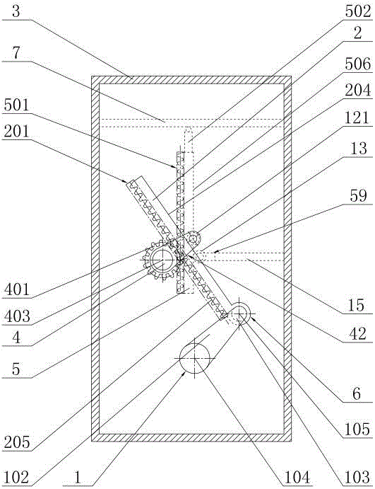
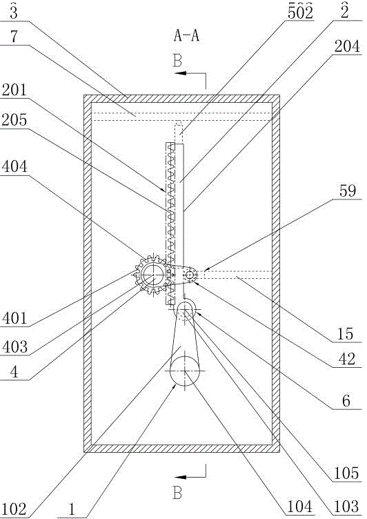
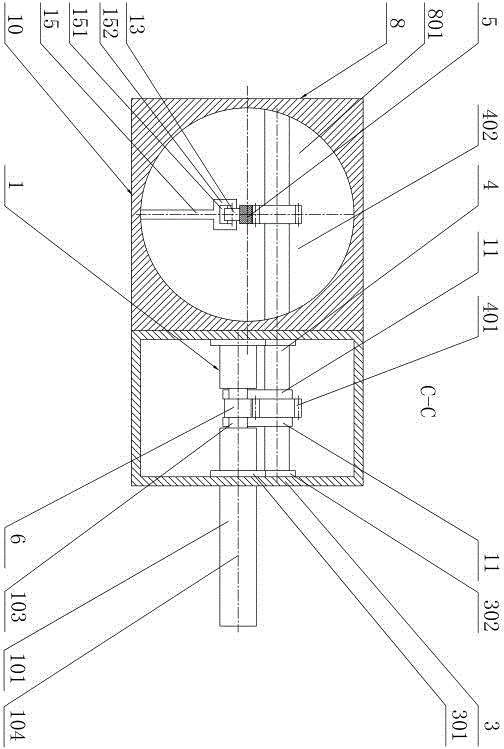
[0037] Such as figure 1 , 2 , 3, and 4, the operating process of the first embodiment of the present invention is as follows: the main journal 101 of the crankshaft 1 is rotatably installed on the two side walls of the crankcase 3, and a rack joint 6 is arranged at one end of the main rack 2, The rack journal 103 at the end of the crank arm 102 is hinged with the main rack 2 by means of the rack joint 6. The transmission shaft 4 is installed in the bearings 301 on the two side walls of the crankcase 3. 201 meshes with the main gear 401 arranged on the cylindrical surface of the transmission shaft 4, and a limit mechanism 42 is arranged between the main rack 2 and the main gear 401; Cylinder block 9, power transmission shaft 4 ...


PUM


Abstract

The invention discloses a gear-rack-crankshaft linkage engine conversion mechanism. According to the gear-rack-crankshaft linkage engine conversion mechanism, a rack journal 103 of a crankshaft 1 in a crankshaft shell 3 is hinged to one end portion of a main rack 2; a main tooth row 201 of the main rack 2 is engaged with a main gear 401 of a transmission shaft 4; a limiting mechanism 42 is arranged between the main rack 2 and the main gear 4; multiple gears 402 of the transmission shaft 4 in a transmission cylinder 9 are engaged with rack connecting rods 5; limiting mechanisms 59 are arranged between the gears 402 and the rack connecting rods 5; on end portion or two end portions of each rack connecting rod 5 is/are connected with one end portion of an additional connecting rod 502; all the additional connecting rods 5-2 are hinged to pistons 7 in the air cylinders 801; and the total acting force on the pistons 7 is transmitted to the main tooth row 201 through the rack connecting rods 5, the gears 402 and the main gear 401 and drives the rack journal 103 of the crankshaft 1 to do the circular movement, and an engine set of the multiple air cylinders 801 is formed.

Description

technical field [0001] The invention relates to a mechanical device for converting the piston reciprocating linear motion of an engine into the circular motion of a crankshaft, in particular to a gear-rack-crankshaft linkage engine conversion mechanism, which replaces the existing crankshaft (handle)-connecting rod conversion mechanism. Background technique [0002] At present, piston engines generally use the crankshaft (crank) connecting rod mechanism to convert linear reciprocating motion and circular motion. The design and manufacture of the crankshaft connecting rod mechanism have been perfected. The force state is very complicated, and each component is in a complex three-way stress state. There are still obvious defects in practical applications, which need to be further improved and optimized: 1. In the existing crankshaft and connecting rod mechanism, after the gas in the cylinder is ignited, Only about 20% of the maximum gas pressure on the piston is decomposed int...

Claims


Application Information

Patent Timeline
Patent Type & Authority Applications(China)
IPC IPC(8): F16H37/16F02B75/32
CPCF02B75/32F16H37/16
Inventor 安里千刘庆王聪毛灵涛刘升贵
Owner 安里千
Why Eureka
Try Eureka