Blowing and inhaling type welding fume dust removal system

A technology of dust removal system and welding fume, which is applied in the direction of gas treatment, separation of dispersed particles, chemical instruments and methods, etc. It can solve the problems of inability to completely solve the problem of dust removal, small particle size of welding fume, high one-time investment, etc.

Inactive Publication Date: 2017-05-31
BEIJING TIMELAND GENERAL EQUIP CO LTD
View PDF6 Cites 11 Cited by
  • Summary
  • Abstract
  • Description
  • Claims
  • Application Information

AI Technical Summary

Problems solved by technology

[0002] The treatment of welding fume is a comprehensive problem. The difficulty lies in: 1. The particle size of welding fume is small, and its particle size is 0.01-10um, so it is difficult to filter and purify; 2. The variability of welding stations, many welding stations, welding The large workpiece makes it difficult to capture welding fume; 3. The welding workpiece has large dimensions and large welding area, making it difficult to capture welding fume; 4. There is a maximum concentration zone of fume in the welding workshop, and it is difficult to remove dust with common ventilation technology; 5. Welding with oil fume It is very difficult to purify smoke and dust; 6. Auxiliary equipment takes up a lot of space, and various pipelines are full of workshops; 7. The loading and unloading of workpieces requires special hoisting equipment, and the logistics is complicated
[0003] The treatment methods for dealing with welding fumes in the existing industry include: 1. Local ventilation and dust removal methods, which are greatly restricted by site layout, operator habits and equipment movement space; the protection objects are limited to welding workers, and the entire workshop environment cannot be improved; space requirements The laying of pipelines is limited by the con

Method used


Image

  • Blowing and inhaling type welding fume dust removal system
  • Blowing and inhaling type welding fume dust removal system
  • Blowing and inhaling type welding fume dust removal system

Examples


Embodiment Construction

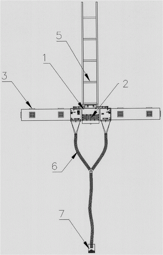
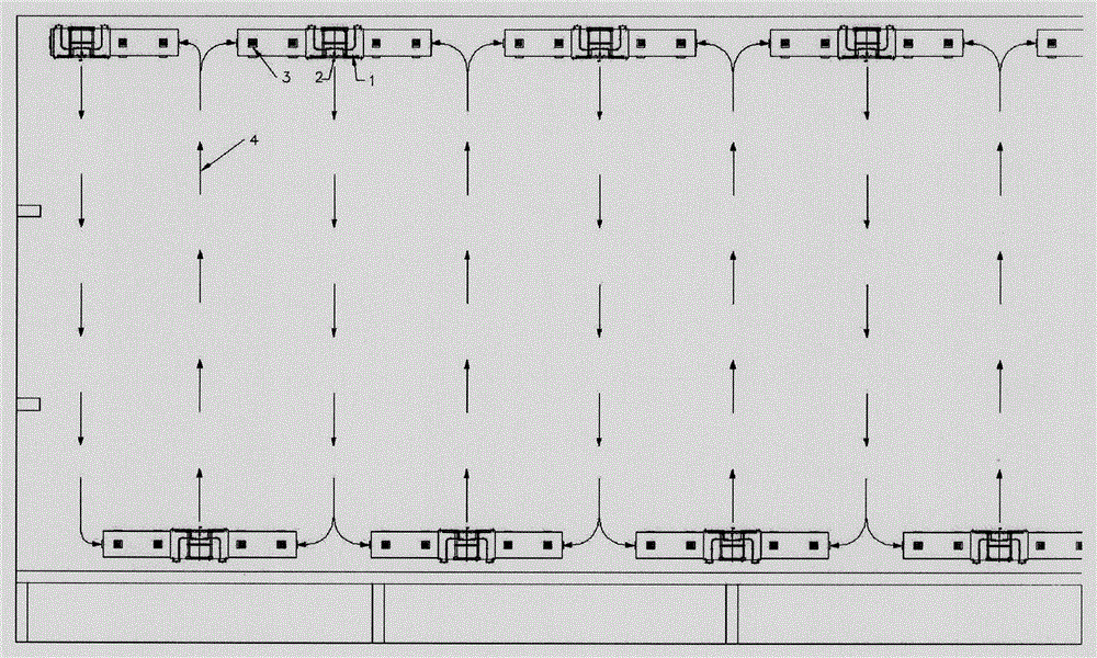
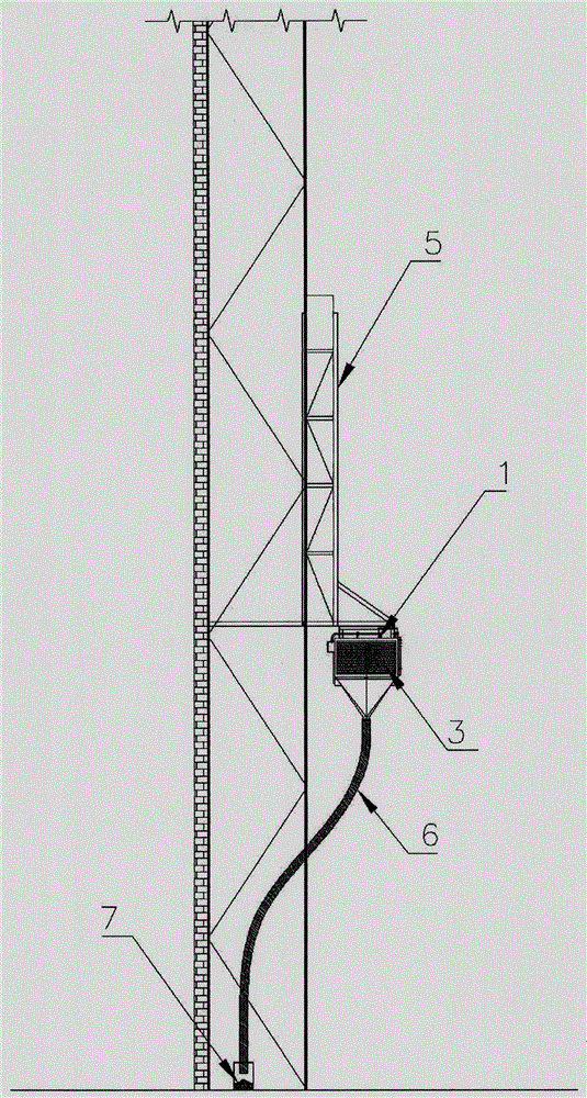
[0011] Referring to the accompanying drawings, the blowing and suction welding fume dust removal system includes a dust collector 1, a blowing port 2, a suction port 3, a jet 4, a hanging bracket 5, a hose 6, and an ash hopper 7; The suction type welding fume dust removal system is characterized in that at a certain height of the factory building, multiple air outlets 2 and suction outlets 3 are arranged in a W-shaped row on both sides, and the air is injected into a large space through the air outlets 2 to form a staggered direction with the same forward direction. Multiple parallel jets 4; after reaching a certain distance, each jet merges with the suction flow to form a fixed airflow path, so that the jet can only develop in the longitudinal direction, so the movement of the jet in this area is similar to the plane movement, forming a horizontal Air barrier; due to the large space of the factory building and the large number of air outlets arranged, after the jets 4 converge...


PUM


Abstract

The invention relates to a welding fume dust removal system and especially relates to a blowing and inhaling type welding fume dust removal system. For solving the problems that the welding fume is small in particle size, welding work stations are large in number, welding work pieces are large in size, and the welding fume is difficult to capture, the invention provides the blowing and inhaling type welding fume dust removal system, which utilizes jet flow as power and transports harmful substances, such as the welding fume, to an air suction port; and then the welding fume is filtered and discharged through an electrostatic dust remover. In addition, diffusion of the harmful substances, such as the welding fume, is inhibited and controlled by the jet flow. The system integrates both air flow blowing and inhalation, wherein the air blowing port is arranged opposite to the air suction port to form blowing and inhaling air flow, which is used for inducing, controlling and filtering the air flow of the harmful substances, such as the welding fume.

Description

technical field [0001] The invention relates to a welding fume dedusting system, in particular to a blowing and suction type welding fume dedusting system. Background technique [0002] The treatment of welding fume is a comprehensive problem. The difficulty lies in: 1. The particle size of welding fume is small, and its particle size is 0.01-10um, so it is difficult to filter and purify; 2. The variability of welding stations, many welding stations, welding The large workpiece makes it difficult to capture welding fume; 3. The welding workpiece has large dimensions and large welding area, making it difficult to capture welding fume; 4. There is a maximum concentration zone of fume in the welding workshop, and it is difficult to remove dust with common ventilation technology; 5. Welding with oil fume It is very difficult to purify smoke and dust; 6. Auxiliary equipment takes up a lot of space, and various pipelines are full of workshops; 7. The loading and unloading of workp...

Claims


Application Information

Patent Timeline
IPC IPC(8): B01D50/00B01D46/42B01D46/48
CPCB01D50/00B01D46/42B01D46/48B01D2258/02B01D2258/0283
Inventor 龚国庆
Owner BEIJING TIMELAND GENERAL EQUIP CO LTD
Why Eureka
Try Eureka