Ammonia spraying device of SCR (selective catalyst reduction) flue gas denitration system

A technology for denitration and flue gas, which is applied in the field of denitration devices, can solve the problems of difficult and uniform mixing, insufficient mixing effect, etc., and achieves the effects of convenient installation and uniform ammonia ejection.

Active Publication Date: 2017-05-31
STATE GRID HENAN ELECTRIC POWER ELECTRIC POWER SCI RES INST +2
View PDF7 Cites 4 Cited by
  • Summary
  • Abstract
  • Description
  • Claims
  • Application Information

AI Technical Summary

Problems solved by technology

However, this device achieves the purpose of mixing by setting a spoiler with an angle α with the direction of the flue gas, and the ammonia and flu...

Method used


Image

  • Ammonia spraying device of SCR (selective catalyst reduction) flue gas denitration system
  • Ammonia spraying device of SCR (selective catalyst reduction) flue gas denitration system
  • Ammonia spraying device of SCR (selective catalyst reduction) flue gas denitration system

Examples


Embodiment 1

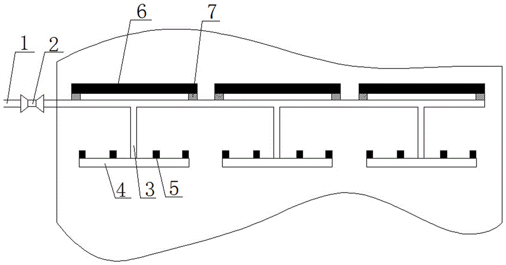
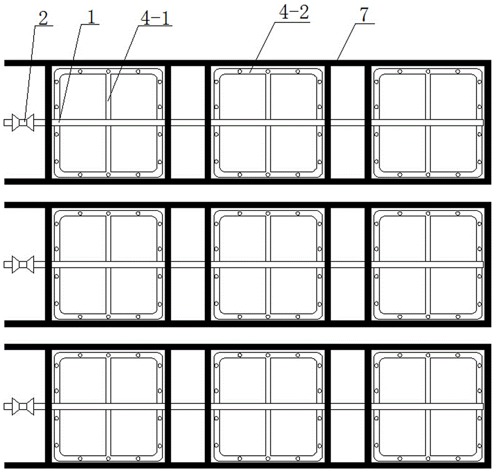
[0036] Such as Figure 1-3 As shown, an ammonia injection device for an SCR flue gas denitrification system includes a plurality of input pipes 1 uniformly arranged in the flue and a plurality of uniformly distributed ammonia injection units connected to the input pipes 1, wherein each input pipe 1 is provided with Valve 2; a spoiler 6 is arranged above each ammonia injection unit, and the spoiler 6 is fixed on the input pipe 1 through a support structure 7 .

[0037] The ammonia injection unit includes a closed nozzle 4 and a branch pipe 3 connecting the input pipe 1 and the closed nozzle 4. The closed nozzle 4 includes an annular pipe 4-2 connected end to end and a central pipe 4-1, wherein the central pipe 4 -1 The two ends of the head and the tail are respectively communicated with the annular pipe 4-2, and the input pipe 1 and the central pipe 4-1 on the closed nozzle 4 are communicated through the branch pipe 3; wherein the annular pipe 4-2 can be a regular circle Ring ...

Embodiment 2

[0042] Embodiment 2 is basically the same structure as Embodiment 1, except that the structure of the nozzle is different, such as Figure 8 As shown, the nozzle 5 is provided with a plurality of spouts 5-1 evenly distributed along the axis of the nozzle 5. In this embodiment, the number of spouts is 4, and the automatic control shrapnel 5-2 is set in the spout 5-1, and the automatic control shrapnel 5-1 2 One end is hinged with the inner wall of the spout 5-1, and the other end is in contact with the stopper 5-3 arranged on the inner wall of the spout 5-1. Since the direction of injecting ammonia gas from the spout is horizontal and perpendicular to the direction of the smoke, it can enhance The mixing intensity of ammonia gas and flue gas; In addition, the setting of the shrapnel is automatically controlled. When the valve 2 is opened and ammonia gas is sprayed, the internal pressure of the nozzle 5 is stronger than the internal pressure of the flue, and the opening of the sh...


PUM


Abstract

The invention discloses an ammonia spraying device of an SCR (selective catalyst reduction) flue gas denitration system. The ammonia spraying device comprises a plurality of input pipes (1) and a plurality of groups of uniformly distributed ammonia spraying units, wherein the input pipes (1) are uniformly arranged in a flue; the ammonia spraying units are connected with the input pipes (1) and are uniformly distributed; a spoiler (6) is arranged above each ammonia spraying unit; each ammonia spraying unit comprises a closing type spray pipe (4) and a branch pipe (3), and each branch pipe (3) is used for connecting the corresponding input pipe (1) and the corresponding closing type spray pipe (4); a spray nozzle (5) is arranged on each closing type spray pipe (4); each spoiler (6) comprises a casing and a plurality of blades arranged on the casing, and each blade (10) is of an arc-shaped trapezoidal structure. The ammonia spraying device has the advantages that by arranging the spoilers in the ammonia spraying device, flue gas can be fully and comprehensively mixed with ammonia gas in short distance, so that the additional arrangement of a static mixer is not needed, and the cost is low; by arranging the ammonia spraying device, the reverse flowing of the flue gas into an ammonia spraying pipeline is prevented.

Description

technical field [0001] The invention relates to the technical field of denitrification devices, in particular to an ammonia injection device for an SCR flue gas denitrification system. Background technique [0002] The emission of nitrogen oxides will cause a series of environmental problems and cause serious harm to people's health. From a global perspective, fuel combustion represented by coal is one of the main sources of nitrogen oxides in the atmosphere, and the selective catalytic reduction denitrification technology (SCR) has been widely used due to its simple structure, convenient operation, and high reliability. In commercial applications, the uniform mixing of reducing agent and nitrogen oxides and the flow field distribution of flue gas are one of the key factors affecting the denitrification efficiency. At present, ammonia injection grids are widely used to ensure the removal efficiency of nitrogen oxides. However, due to the large number of reductant injection...

Claims


Application Information

Patent Timeline
IPC IPC(8): B01D53/86B01D53/90B01D53/56
CPCB01D53/8631B01D53/90B01D2258/0283Y02A50/20
Inventor 任利明张步庭杜学森黄永志周海远李敏刘静宇胡胜林詹胜平张君正陈青
Owner STATE GRID HENAN ELECTRIC POWER ELECTRIC POWER SCI RES INST
Why Eureka
Try Eureka