Inorganic chemical wastewater treatment tank capable of improving cleanness of wastewater

A technology for chemical wastewater and treatment tank, which is applied in water/sewage treatment, water/sewage multi-stage treatment, water/sludge/sewage treatment, etc. It can solve the problems of low clarity of wastewater, inconvenient operation, and installation at the bottom, etc. Achieve the effect of improving water treatment efficiency, slag discharge efficiency, and increasing wastewater flow rate

Inactive Publication Date: 2017-05-31
CHENGDU YANXINGGUO TECH CO LTD
View PDF1 Cites 23 Cited by
  • Summary
  • Abstract
  • Description
  • Claims
  • Application Information

AI Technical Summary

Problems solved by technology

[0005] The present invention overcomes the deficiencies of the prior art and provides an inorganic chemical wastewater treatment tank that discharges sludge from above and is convenient for sewage discharge operation, and solves the problem that the sewage outlet of the existing wastewater treatment tank is located at the bottom, which is inconvenient to operate and the waste water clarity is low The problem

Method used


Image

  • Inorganic chemical wastewater treatment tank capable of improving cleanness of wastewater

Examples


Embodiment 1

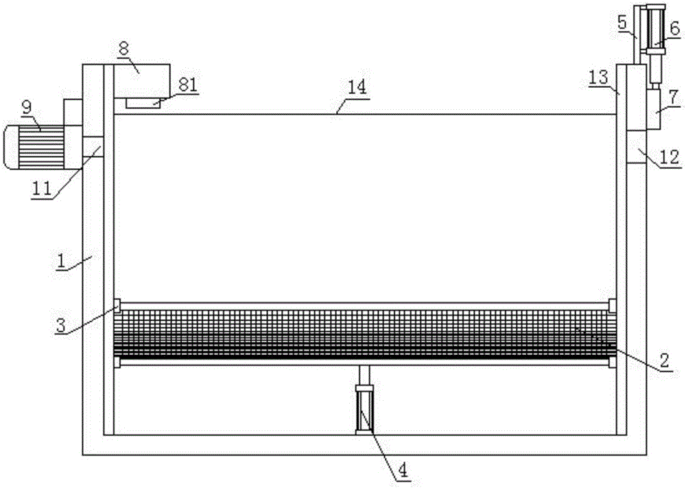
[0021] Such as figure 1 As shown, the present invention includes a settling tank 1, one end of the settling tank 1 is provided with a water inlet 11, the other end of the settling tank 1 is provided with a water outlet 12, and the side wall of the settling tank 1 is provided with a chute 13. A filter screen 2 is arranged obliquely, and the side of the sedimentation tank 1 close to the lower end of the filter screen 2 is provided with a slag outlet 14, and the edge of the filter screen 2 is connected with a slider 3, and the slider 3 is sleeved in the chute 13; the sedimentation tank 1 bottom is equipped with lifting cylinder 4, and the piston rod of lifting cylinder 4 is fixed on filter screen 2 bottoms.

[0022] The sedimentation tank 1 of the present invention is provided with a chute 13 , and the filter screen 2 can rise or fall in the chute 13 under the drive of the lifting cylinder 4 . Thereby, the inclined filter screen 2 can push the settled sludge out from the slaggin...

Embodiment 2

[0024] Such as figure 1 As shown, the present invention includes a settling tank 1, one end of the settling tank 1 is provided with a water inlet 11, the other end of the settling tank 1 is provided with a water outlet 12, and the side wall of the settling tank 1 is provided with a chute 13. A filter screen 2 is arranged obliquely, and the side of the sedimentation tank 1 close to the lower end of the filter screen 2 is provided with a slag outlet 14, and the edge of the filter screen 2 is connected with a slider 3, and the slider 3 is sleeved in the chute 13; the sedimentation tank 1 bottom is equipped with lifting cylinder 4, and the piston rod of lifting cylinder 4 is fixed on filter screen 2 bottoms. The sedimentation tank 1 of the present invention is provided with a chute 13 , and the filter screen 2 can rise or fall in the chute 13 under the drive of the lifting cylinder 4 . Thereby, the inclined filter screen 2 can push the settled sludge out from the slagging outlet ...

Embodiment 3

[0027] Such as figure 1 As shown, the present invention includes a settling tank 1, one end of the settling tank 1 is provided with a water inlet 11, the other end of the settling tank 1 is provided with a water outlet 12, and the side wall of the settling tank 1 is provided with a chute 13. A filter screen 2 is arranged obliquely, and the side of the sedimentation tank 1 close to the lower end of the filter screen 2 is provided with a slag outlet 14, and the edge of the filter screen 2 is connected with a slider 3, and the slider 3 is sleeved in the chute 13; the sedimentation tank 1 bottom is equipped with lifting cylinder 4, and the piston rod of lifting cylinder 4 is fixed on filter screen 2 bottoms. The sedimentation tank 1 of the present invention is provided with a chute 13 , and the filter screen 2 can rise or fall in the chute 13 under the drive of the lifting cylinder 4 . Thereby, the inclined filter screen 2 can push the settled sludge out from the slagging outlet ...


PUM


Abstract

The invention relates to the field of wastewater treatment and in particular relates to an inorganic chemical wastewater treatment tank capable of improving the cleanness of wastewater. The inorganic chemical wastewater treatment tank capable of improving the cleanness of the wastewater, provided by the invention, is characterized by comprising a sedimentation tank; a water inlet is arranged at one end of the sedimentation tank and a water outlet is arranged at the other end of the sedimentation tank; a sliding groove is formed in a side wall in the sedimentation tank; a filtering screen is obliquely arranged in the sedimentation tank; a dreg discharging hole is formed in one side, close to the lower end of the filtering screen, of the sedimentation tank; the edge of the filtering screen is connected with a sliding block; the sliding groove is arranged in the sliding block in a sleeving manner; a hoisting air cylinder is mounted at the bottom of the sedimentation tank; a piston rod of the hoisting air cylinder is fixed at the bottom of the filtering screen. According to the inorganic chemical wastewater treatment tank provided by the invention, the disadvantages in the prior art are overcome, and the inorganic chemical wastewater treatment tank capable of discharging sludge from the upper side and convenient for blow-off operation is provided; the problems that a blow-off hole of an existing wastewater treatment tank is arranged at the lower side and the clarification degree of the wastewater is low are solved.

Description

technical field [0001] The invention relates to the field of waste water treatment, in particular to an inorganic chemical waste water treatment pool for improving the cleanliness of waste water. Background technique [0002] The sedimentation tank for wastewater treatment is a structure that uses sedimentation to remove pollutants in water, and is widely used in sewage treatment. At present, the commonly used sedimentation tank is an advection flow structure, which has the advantages of good hydraulic conditions and stable sedimentation effect; its sedimentation efficiency and separation effect are related to the static separation area and time. To obtain high sedimentation efficiency, there must be sufficient sedimentation area and resting separation time. [0003] The invention patent with the patent application number CN201520259125.6 discloses a sludge sedimentation tank, which includes: the first sedimentation tank, the second sedimentation tank, the third sedimentati...

Claims


Application Information

Patent Timeline
Patent Type & Authority Applications(China)
IPC IPC(8): C02F9/04B01D36/04B01D21/01C02F1/52C02F1/00
CPCC02F1/52B01D21/0006B01D21/0012B01D21/01C02F1/001C02F1/5245C02F1/5254C02F2001/007
Inventor 魏霁烁柏雅惠
Owner CHENGDU YANXINGGUO TECH CO LTD
Why Eureka
Try Eureka