Spiral trench-shaped electrostatic spinning device and use method of same

A spiral groove and electrospinning technology, applied in textiles and papermaking, filament/thread forming, fiber processing, etc., can solve the fluctuation of solvent volatilization concentration of the solution to be spun, non-oriented structure of nanofiber products, and low output of nanofibers and other issues, to achieve the effect of automatic supply and control, strengthened control, and convenient operation

Active Publication Date: 2017-05-31
DONGHUA UNIV
View PDF8 Cites 18 Cited by
  • Summary
  • Abstract
  • Description
  • Claims
  • Application Information

AI Technical Summary

Problems solved by technology

[0006] The technical problem to be solved by the present invention is to provide a spiral groove electrospinning device and its use method, through the spiral groove nozzle on the upper end of the cylindrical seat, to solve the problem that the relative free liquid surface is too large in the current electrospinning process, the free liquid There is a lot of solution to be spun in the surface, the volatilization concentration of the solvent in the solution to be spun fluctuates during the long-term spinning process, the output of nanofibers per unit area per unit time is low, and the final nanofiber product structure has no orientation.

Method used


Image

  • Spiral trench-shaped electrostatic spinning device and use method of same
  • Spiral trench-shaped electrostatic spinning device and use method of same

Examples


Embodiment 1

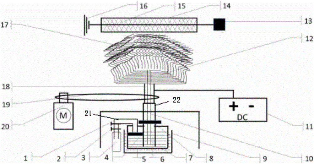
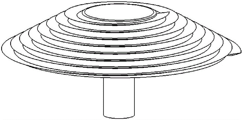
[0034] like figure 1 and figure 2As shown, a spiral groove electrospinning device includes a liquid supply system, a spiral groove spinning system and a nanofiber collection system, wherein the liquid supply system includes a gas cylinder 3, a spinning solution storage bottle 7, Oil bath 9 and catheter 10, described spinning solution storage bottle 7 is arranged in the oil bath 9, and described catheter 10 passes through rotating shaft 18, and one end is arranged on the bottom of spinning solution storage bottle 7, The other end is arranged on the top of the spiral groove nozzle 12, and the spinning solution storage bottle 7 and the catheter 10 form a connector structure to the top of the spiral groove nozzle 12, and the spinning solution storage bottle 7 passes through the trachea 21 and The gas cylinder 3 is connected, and the air pipe 25 is provided with a main valve 2 and a pressure reducing valve 1 in turn near the gas cylinder 3. The spiral groove spinning system inclu...

Embodiment 2

[0052] Next, nanofibers are prepared by using a polymer solution prepared from polyacrylonitrile (PAN) and N-N dimethylformamide (DMF). The mass fraction of the prepared PAN polymer solution is 10%. The configured PAN / DMF polymer solution is injected into the spinning solution storage bottle 7, and the spinning solution storage bottle 7 and the spiral groove nozzle 12 are connected with the catheter 10. Add silicone oil 5 into the oil bath 9, and heat it to the set temperature of 40° C. with a hot stage. Open the middle switch 8 of the catheter tube 10, open the main valve 2 of the gas cylinder 3, adjust the pressure reducing valve 1 to push the piston 4 so that the high polymer solution 6 slowly flows into the spiral groove nozzle 12 through the catheter tube 10, so that the high polymer solution The substance solution 6 is present in a certain amount in the spiral groove-shaped shower head 12. Connect the metal drum 14 to the ground wire 16, turn on the motor 13 connected ...

Embodiment 3

[0054] Next, nanofibers are prepared by using a polymer solution prepared from polyacrylonitrile (PAN) and N-N dimethylformamide (DMF). The mass fraction of the prepared PAN polymer solution is 12%. The configured PAN / DMF polymer solution is injected into the spinning solution storage bottle 7, and the spinning solution storage bottle 7 and the spiral groove nozzle 12 are connected with the catheter 10. Add silicone oil 5 into the oil bath 9, and heat it to the set temperature of 30° C. with a hot stage. Open the middle switch 8 of the catheter tube 10, open the main valve 2 of the gas cylinder 3, adjust the pressure reducing valve 1 to push the piston 4 so that the high polymer solution 6 slowly flows into the spiral groove nozzle 12 through the catheter tube 10, so that the high polymer solution The substance solution 6 is present in a certain amount in the spiral groove-shaped shower head 12. Connect the metal drum 14 to the ground wire 16, turn on the motor 13 connected ...


PUM

PropertyMeasurementUnit
diameteraaaaaaaaaa
lengthaaaaaaaaaa
heightaaaaaaaaaa

Abstract

The invention relates to a spiral trench-shaped electrostatic spinning device comprising a liquid supplying system, a spiral trench-shaped spinning system and a nano-fiber collecting system. The liquid supplying system has an air bottle, a spinning liquid storage bottle, an oil bath groove and a liquid guiding pipeline; the liquid guiding pipe is disposed in the oil bath groove; the liquid guiding pipe passes through a rotating shaft; the upper end of the liquid guiding pipe is arranged on the bottom of the spinning liquid storage bottle and the lower end is arranged on the top of a spiral trench-shaped sprayer; the spinning liquid storage bottle and the liquid guiding pipe form a connector structure on the top of the spiral trench-shaped sprayer; the spinning liquid storage liquid is connected with the air bottle via an air pipe; a total valve and a reducing valve are orderly arranged on a place on the air pipe and close to the air bottle; and the spiral trench-shaped spinning system has a motor, a transmission belt, a rotating shaft, a spiral trench-shaped sprayer and a cylindrical seat. High-polymer solution can be automatically fed by the sprayer and controlled with liquid supplying system connected with the top of the spiral trench-shaped sprayer via the air-pressure connector; and the spiral trench-shaped electrostatic spinning device can be simply operated and easy to handle.

Description

technical field [0001] The invention belongs to the technical field of nano electrospinning and textile machinery, and in particular relates to a spiral groove electrospinning device and an application method thereof. Background technique [0002] When polymer fiber diameters are reduced from the micrometer scale to the submicrometer or nanometer scale, a surprising set of properties emerges. Such as a very large volume specific surface area, the volume specific surface area of ​​nanofibers is basically 1000 times that of microfibers; it can be flexibly functionalized on the surface; it shows superior effects and mechanical properties compared with other known material forms, such as surface And interface effect, small size effect, quantum size effect and quantum tunneling effect and stiffness, tensile strength, etc. These outstanding properties make nanofibers the material of choice for many important applications, and have great development potential in the fields of high...

Claims


Application Information

Patent Timeline
Patent Type & Authority Applications(China)
IPC IPC(8): D01D5/00
CPCD01D5/0061D01D5/0069D01D5/0076
Inventor 覃小红熊健
Owner DONGHUA UNIV
Why Eureka
Try Eureka