Intelligent control device applied to oil-field pumping unit
An intelligent control and pumping unit technology, which is applied in the direction of AC motor control, pump control, control system, etc., can solve the problems of no obvious increase in oil production or energy saving in oil fields, affecting oil well production, and increased leakage, and achieves strong practicality Performance and promotion value, improve pumping efficiency and oil production, improve the effect of pump efficiency
- Summary
- Abstract
- Description
- Claims
- Application Information
AI Technical Summary
Problems solved by technology
Method used
Image
Examples
Embodiment 1
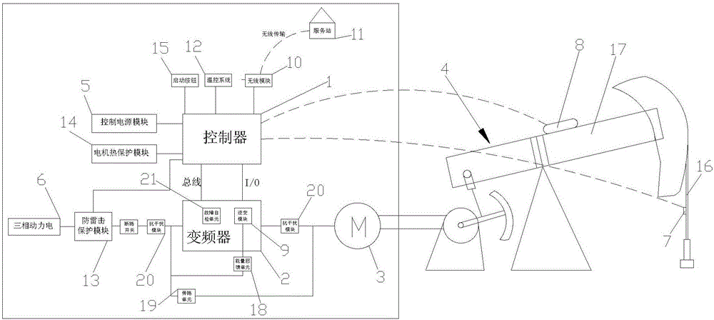
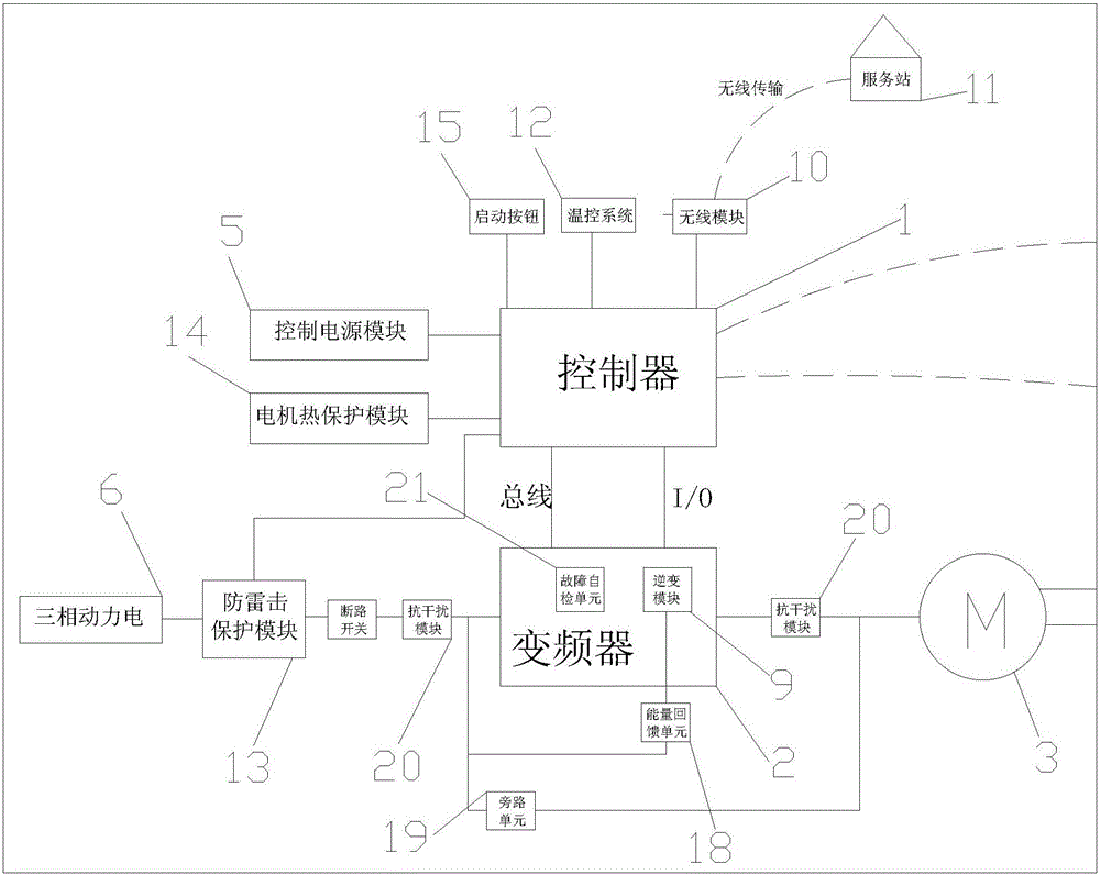
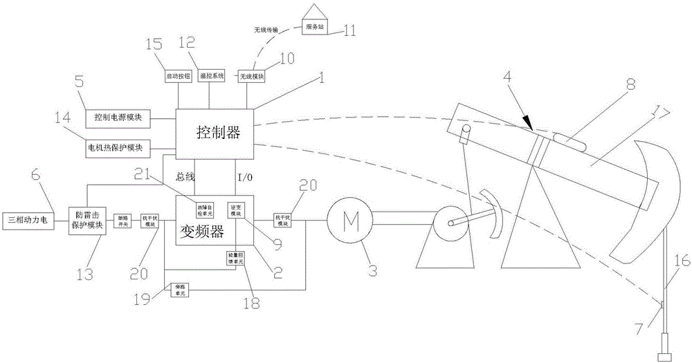
[0028] When working, first calculate the highest and lowest positions of the sucker rod 16 through the controller 1 through the data transmission of the sensor 8, and then set the speed of the upstroke and downstroke of the sucker rod 16 according to the actual oil output of the oil well; then The pumping unit starts to work. When the sucker rod 16 in the pumping unit 4 is pulled to the highest position, the position measured by the sensor 8 is fed back to the controller 1, and the controller 1 sends a low-speed signal to the inverter 2, and the inverter 2 controls the motor 3. Run at a low speed, so that the time when the sucker rod 16 reaches the lowest position can fully allow the oil well to penetrate the oil, ensure that the liquid in the pump barrel is full, and ensure the pumping efficiency; when the sucker rod 16 in the pumping unit 4 is pulled to The lowest position, the position measured by the sensor 8 is fed back to the controller 1, the controller 1 sends high and ...
Embodiment 2
[0030] When in use, the data from the sensor (8) is first transmitted to the controller (1), and the controller (1) adjusts the high-speed value and low-speed value of the frequency converter (2), combined with the data from the load sensor (7), the controller (1) ) internally calculates the dynamometer diagram, and when it is found that the dynamometer diagram area is not the largest, adjust the high-speed value and low-speed value of the frequency converter again until the optimal dynamometer diagram is obtained, so as to automatically determine the upstroke of the sucker rod (16) and The speed of the down stroke; then the pumping unit starts to work, when the sucker rod 16 is pulled to the highest position, the sensor 8 sends a signal to the controller 1, and the controller 1 controls the motor 3 through the frequency converter 2 at the lower speed calculated by the controller 1 Stroke speed operation; when the sucker rod 16 is pulled to the lowest position, the sensor 8 sen...
PUM
 Abstract
Description
Claims
Application Information
 - R&D
- Intellectual Property
- Life Sciences
- Materials
- Tech Scout
- Unparalleled Data Quality
- Higher Quality Content
- 60% Fewer Hallucinations
Browse by: Latest US Patents, China's latest patents, Technical Efficacy Thesaurus, Application Domain, Technology Topic, Popular Technical Reports.
© 2025 PatSnap. All rights reserved.Legal|Privacy policy|Modern Slavery Act Transparency Statement|Sitemap|About US| Contact US: help@patsnap.com


