Electro-hydraulic hybrid driven electric shovel hoisting system

A technology of electro-hydraulic mixing and hoisting system, which is applied in open-pit mining, earthwork drilling, special mining, etc. It can solve the problems of high peak current of hoisting device, grid current impact, harmonic interference, etc., so as to improve work reliability and stability, improve work stability, and reduce the effect of installed power

Inactive Publication Date: 2017-05-31
TAIYUAN UNIV OF TECH
View PDF5 Cites 14 Cited by
  • Summary
  • Abstract
  • Description
  • Claims
  • Application Information

AI Technical Summary

Problems solved by technology

However, since the electric shovel will randomly feed power to the power grid during its movement, and the peak current of the lifting device is still very large, it will cause a large current impact and harmonic interference to the power grid, which will affect the working stability and reliability of the electric shovel.
[0004] Similarly, a Chinese invention patent published by the National Patent Office in 2015, a mining excavator lifting mechanism, publication number: CN104555774A, discloses a transmission device for a new type of mining excavator lifting mechanism, which optimizes the lifting mechanism. structure, starting from reducing the weight of the lifting mechanism to achieve the purpose of energy saving and emission reduction, but although the weight reduction can reduce part of the energy consumption, it does not make full use of the electric energy generated by the electric shovel lifting device
[0005] The above two energy-saving methods did not reduce the installed power and peak current of the electric shovel lifting motor, nor did they make full use of the potential energy of the electric shovel during its descent

Method used


Image

  • Electro-hydraulic hybrid driven electric shovel hoisting system
  • Electro-hydraulic hybrid driven electric shovel hoisting system
  • Electro-hydraulic hybrid driven electric shovel hoisting system

Examples


Embodiment 1

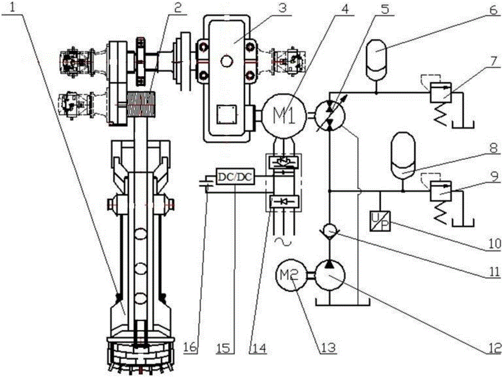
[0018] Example 1: figure 1 As shown, the electric shovel lifting system driven by electro-hydraulic hybrid includes bucket 1, lifting reel 2, speed reducer 3, lifting motor 4, hydraulic pump / motor 5, high-pressure accumulator group 6, the first overflow valve 7, Low pressure accumulator group 8, second relief valve 9, pressure sensor 10, check valve 11, charge pump 12, charge pump motor 13, frequency converter 14, DC / DC converter 15, super capacitor group 16. The hydraulic pump / motor 5 is placed on the output shaft of any transmission shaft between the reducer and the motor, as attached figure 1 As shown, the outline drawing of the hydraulic pump / motor drawn by the dotted line indicates the position where the hydraulic pump / motor 5 can be placed. If the hydraulic pump / motor is directly connected to the lifting motor 4, the lifting motor 4 is a double-outlet shaft motor. The DC / DC converter 15 is connected to the DC bus of the hoisting motor 4 frequency converter 14, and the D...

Embodiment 2

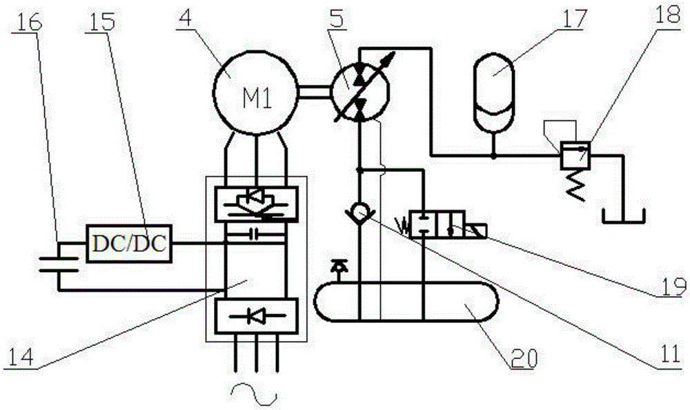
[0023] Example 2: figure 2 As shown, the working principle of this embodiment is similar to that of Embodiment 1, and the difference is that the charging pump 12, the charging pump motor 13, the high-pressure accumulator group 6 and the first overflow valve 7, the low-pressure accumulator group 8 and the first overflow valve 7 are eliminated. II Relief valve 9, increase two-position two-way electromagnetic reversing valve 19 and pressurized oil tank 20.

[0024] When the electric shovel bucket falls, the lifting motor 4 is in the power generation state, the DC bus voltage in the frequency converter 14 rises, and the supercapacitor group 16 is charged through the DC / DC converter 15, and at the same time, the hydraulic pump / motor 5 is in pumping operation state, the oil suction port is connected to the one-way valve 11, and the oil discharge port is connected to the accumulator group 17 to store energy for the accumulator group 17, and convert the gravitational potential energy...

Embodiment 3

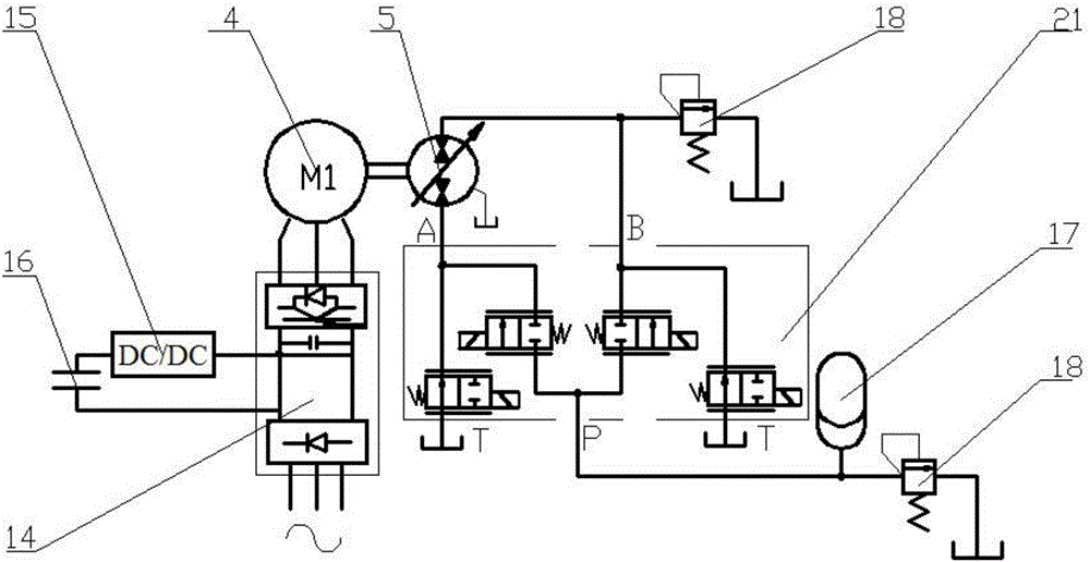
[0026] Example 3: image 3 As shown, the working principle of this embodiment is similar to that of Embodiment 1, and the difference is that the charging pump 12, the charging pump motor 13, the high-pressure accumulator group 6 and the first overflow valve 7, the low-pressure accumulator group 8 and the first overflow valve 7 are eliminated. II Relief valve 9 adds a proportional directional control valve group 21 composed of four two-position two-way proportional directional control valves. The two two-position two-way proportional directional control valves connected to the P port are normally closed, and T The two two-position two-way proportional directional control valves connected to the port are in the normally open state. By adjusting the throttle opening of any one two-position two-way proportional directional control valve, the speed of the hydraulic pump / motor can be adjusted, and the system can be increased at the same time. damping to improve system stability.


PUM


Abstract

The invention provides an electro-hydraulic hybrid driven electric shovel hoisting system and belongs to the field of large equipment for surface mining. The electro-hydraulic hybrid driven electric shovel hoisting system comprises a dipper, a hoisting drum, a speed reducer, a hoisting motor, a hydraulic pump / motor, accumulator groups, an overflow valve, a frequency converter, a DC / DC converter and a super-capacitor group, wherein the DC / DC converter is connected onto a DC bus of the frequency converter and connected with the super-capacitor group; the hydraulic pump / motor is arranged at an output end of any drive shaft between the speed reducer and the hoisting motor, and an oil port of the hydraulic pump / motor is connected with the corresponding accumulator group. According to the electro-hydraulic hybrid driven electric shovel hoisting system, electric energy produced by the hoisting motor during falling of the electric shovel dipper can be stored in the super-capacitor group, so that peak current of an electric shovel motor is reduced, and the working stability of the electric shovel motor is improved. Meanwhile, gravitational potential energy of the electric shovel dipper during falling is converted into hydraulic energy which is stored in the accumulator groups, the energy is used effectively during dipper hoisting to assist motor working, installed power of the electric shovel hoisting motor is reduced, and the working efficiency of the electric shovel is increased.

Description

technical field [0001] The invention belongs to the field of large-scale equipment for open-pit mining, and in particular relates to an electric shovel lifting system driven by electro-hydraulic mixing. Background technique [0002] With the rapid development of the national economy, my country's energy industry, especially the development of the coal industry, has encountered bottlenecks. How to achieve coal mining and transportation with high efficiency and energy saving has become the theme of the current development of the coal industry. The electric shovel (also known as large-scale mining machinery front shovel excavator) has a large bucket capacity, a wide range of operations, strong environmental adaptability, can withstand large vibration and impact loads, high working reliability, and low maintenance costs. It is one of the main equipments in large-scale open-pit coal mines, iron ore and non-ferrous metal mine stripping and mineral mining operations. In the interm...

Claims


Application Information

Patent Timeline
Patent Type & Authority Applications(China)
IPC IPC(8): E21C47/02
CPCE21C47/02
Inventor 权龙王君熊晓燕程珩
Owner TAIYUAN UNIV OF TECH
Why Eureka
Try Eureka