
Piston type axial flow pressure regulator

A piston type, pressure regulator technology, applied in the valve's device for absorbing fluid energy, functional valve type, valve details, etc., can solve the erosion of the throttling part, easy to be damaged by erosion, increase the difficulty of spring manufacturing and production Cost and other issues, to achieve the effect of slowing down strong impact force, prolonging working life, and improving pressure-transformation smoothness and stability

Active Publication Date: 2017-05-31
四川长仪油气集输设备股份有限公司
View PDF11 Cites 8 Cited by
  • Summary
  • Abstract
  • Description
  • Claims
  • Application Information

AI Technical Summary

Problems solved by technology

We have been engaged in the research and development of pressure regulator products and market research for a long time. We also found that: At present, there are domestic or imported axial flow valve products with diaphragm structure as the configuration of pressure regulators. However, due to the high cost of imported axial flow valve products, The maintenance is expensive, the user's engineering cost and use cost are high, and there are deficiencies such as untimely after-sales service; the basic structure of the current axial flow valve is: the convex ring on the outer wall of the adjustment sleeve is fixedly embedded and connected to the diaphragm tray, and the adjustment sleeve The inner hole of the barrel is the medium flow channel, the outer wall is used as a sliding guide, and the end of the barrel is used for throttling and pressure regulation
This kind of pressure regulator that integrates "flow channel, guide and throttling and pressure regulating functions" by the adjusting sleeve still has the following technical structural defects in actual production and field use: First, because the inner hole of the adjusting sleeve is For a channel as large as the caliber of the main valve, the spring can only be installed on the outside of the adjustment sleeve, resulting in an increase in the diameter of the spring, which will greatly increase the difficulty and cost of manufacturing the spring, and the working stability of the spring will also decrease accordingly. This will seriously affect the pressure regulation accuracy and stable performance of the pressure regulator
Second. Due to the long stroke of the adjusting sleeve and the spring, the concentricity is reduced accordingly. It has extremely high requirements on the processing technology, otherwise it will also affect the pressure regulating accuracy and stable performance of the pressure regulator.
Third. It cannot design the multi-stage depressurization of the throttling part, especially under the extreme working conditions of "large pressure difference and small flow", when the gas flow rate increases due to the small opening of the valve port, the high-speed airflow will Serious erosion on the throttling part and rapid damage and failure
Fourth. Because it is a component that integrates multiple functions of "flow channel, guide, throttling and pressure reduction", its working environment is extremely harsh and is easily damaged by erosion. When the adjustment sleeve needs to be repaired and replaced, it must be disassembled. It can only be carried out after the film tray is removed, and the maintenance operation is very troublesome, especially when performing on-site maintenance work on large-caliber pressure regulators, it is laborious and labor-intensive, and the maintenance cost is high

Method used


Image

  • Piston type axial flow pressure regulator
  • Piston type axial flow pressure regulator
  • Piston type axial flow pressure regulator

Examples


Embodiment Construction

[0030] Embodiments of the present invention are further described below in conjunction with the accompanying drawings:

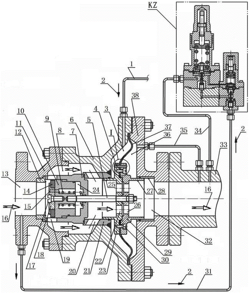
[0031] The piston type axial flow pressure regulator proposed by the present invention is mainly composed of an axial flow regulating valve, a pressure regulating controller KZ and a front pressure signal pipe 31 connected thereto, a rear pressure signal pipe 34, a main regulating signal pipe 1, a backflow Tube 35 is composed.

[0032] The axial flow regulating valve is mainly composed of a main valve body 6, a left valve body 11 installed at both ends of the main valve body 6, a right valve cover 38, a valve seat 12 and a valve sleeve 21 fitted in the main valve body 6, Between the valve seat 12 and the valve sleeve 21, the fixed embedded cylinder liner 7 is divided into an annular axial flow passage 8, and a set of throttle windows 19 communicated with the inlet end of the annular axial flow passage 8 is arranged on the wall of the cylinder liner 7, A set...


PUM


Abstract

The invention discloses a piston type axial flow pressure regulator which mainly comprises an axial flow regulation valve, a pressure regulation controller and a group of signal tubes connected with the pressure regulation controller and has the remarkable structure characteristics that separate flow passage, throttling and depressurizing functional component and guide mechanism functional component are designed in the axial flow regulation valve according to the separation principle. A cylinder sleeve is embedded between a valve seat and a valve sleeve to form an annular flow channel, and a piston is matched in the cylinder sleeve in a sliding manner to carry out pressure regulation and stabilization operation, so that the piston is guaranteed to be applied by the pushing and pulling action force in the axial direction only when sliding in the cylinder sleeve, the defects of large flow resistance, large vibration and high noise as the a turbulent flow is easily generated due to a meander flow passage with lower inlet and upper outlet of the traditional regulation valve are well overcome, and the technical effects of further improving the pressure regulation accuracy and pressure regulation stability are very obvious. The piston type axial flow pressure regulator has the outstanding advantages of simple and rapid structure, liability in production, low manufacturing cost, high pressure regulation accuracy, good stability of output pressure, safety and reliability in running and long service life and has very good popularization and application prospect.

Description

technical field [0001] The invention relates to a gas pressure regulator device, in particular to a piston-type axial flow pressure regulator, which belongs to the technical field of pressure regulation and stabilization of gas transmission pipeline networks, and is especially suitable for installation in natural gas, liquefied gas and CNG pressure regulation stations Perform pressure regulation and stabilization operations on the pipeline. Background technique [0002] The gas pressure regulator is a special equipment installed on the gas pipeline for pressure regulation operation to provide a stable pressure gas source to the downstream pipeline or pipeline network. Most of the most commonly used pressure regulators are composed of the main pressure regulator, the pilot and the signal tube connected to it. Its working principle is: the pressure signal in the downstream gas pipeline is introduced into the pilot by the signal tube. Inside, the pilot changes the opening acco...

Claims


Application Information

Patent Timeline
Patent Type & Authority Applications(China)
IPC IPC(8): F16K17/32F16K31/128F16K47/08
CPCF16K17/32F16K31/128F16K47/08Y02T10/30
Inventor 王元清张月伟魏连康高丽
Owner 四川长仪油气集输设备股份有限公司
Learn More