Pole-piece hot-roll drying system
A drying system and pole piece technology, used in electrode heat treatment, drying solid materials, drying goods processing, etc., can solve the problems of affecting the overall effect of the pole piece, long processing time, insufficient drying treatment of the pole piece, etc., and achieve high uniformity. , The effect of short heating time and fast running speed
- Summary
- Abstract
- Description
- Claims
- Application Information
AI Technical Summary
Problems solved by technology
Method used
Image

Examples
Embodiment Construction
[0040] The specific embodiments of the present invention will be further described below in conjunction with the accompanying drawings. It should be noted here that the descriptions of these embodiments are used to help understand the present invention, but are not intended to limit the present invention. In addition, the technical features involved in the various embodiments of the present invention described below may be combined with each other as long as they do not constitute a conflict with each other.
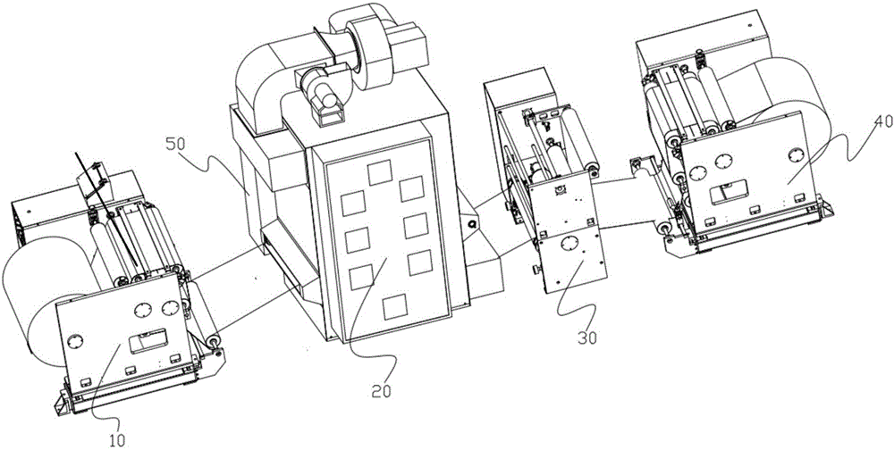
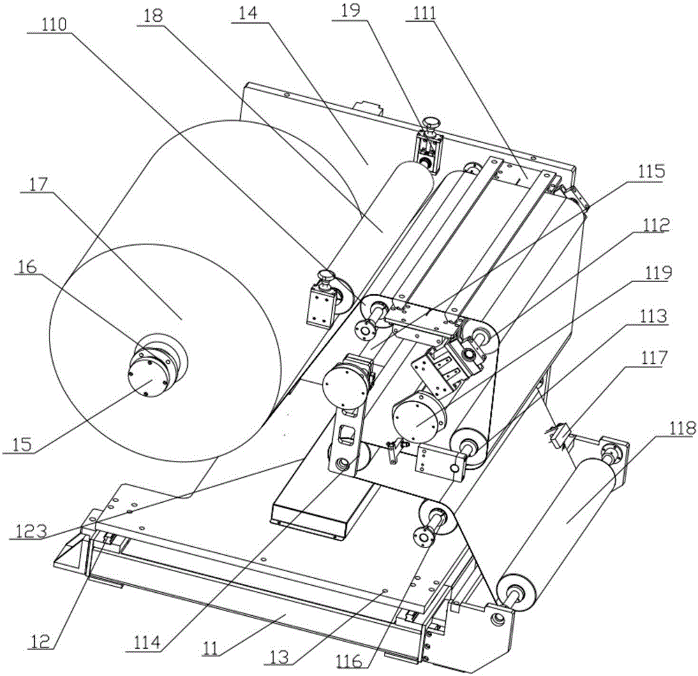
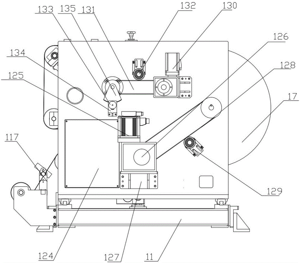
[0041] Reference attached Figure 1-16 , a thermal roller drying system for pole pieces, comprising an unwinding module 10, a hot roller drying furnace module 20, a drive module 30, and a winding module 40; the unwinding module 10 is provided with an unwinding and deviation correction assembly 117 , unwinding pendulum roller 114, unwinding and pressing platform assembly 111, pole piece base tape 12 passes through described unwinding deviation correction assembly 117, de...
PUM
 Abstract
Description
Claims
Application Information
 - Generate Ideas
- Intellectual Property
- Life Sciences
- Materials
- Tech Scout
- Unparalleled Data Quality
- Higher Quality Content
- 60% Fewer Hallucinations
Browse by: Latest US Patents, China's latest patents, Technical Efficacy Thesaurus, Application Domain, Technology Topic, Popular Technical Reports.
© 2025 PatSnap. All rights reserved.Legal|Privacy policy|Modern Slavery Act Transparency Statement|Sitemap|About US| Contact US: help@patsnap.com