Radio frequency coaxial connector and microwave transmission structure
A radio frequency coaxial and connector technology, applied in the direction of connection, connection device, two-part connection device, etc., can solve the problems of lack of inspection means, air cavity impedance matching effect, etc., to reduce the deterioration of standing waves, reduce welding difficulty, reduce The effect of build difficulty
- Summary
- Abstract
- Description
- Claims
- Application Information
AI Technical Summary
Problems solved by technology
Method used
Image
Examples
Embodiment 1
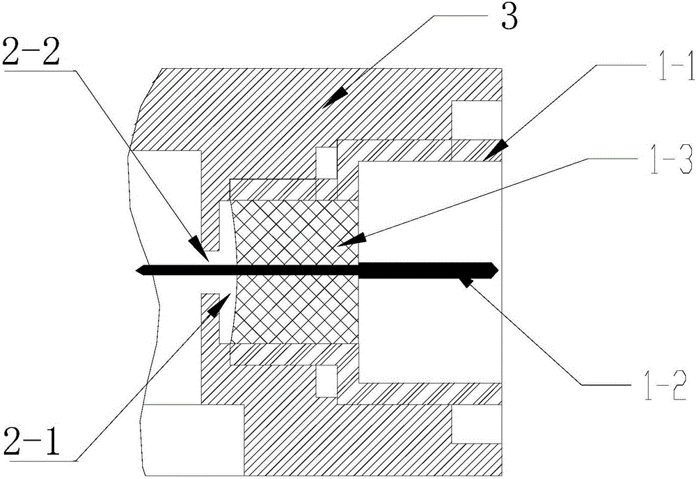
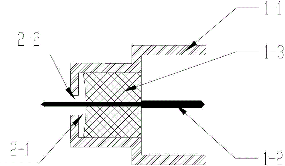
[0014] In Embodiment 1 of the present invention, the air cavity structure originally in the housing installation hole is integrally processed to the end position of the end where the radio frequency coaxial connector is connected to the microstrip line. The air cavity structure is the first air cavity structure 2-1 with an inner diameter of 2 mm and a length of 0.15 mm formed by the part extending from the outer conductor 1-1 of the connector and the insulator 1-3, and the first air cavity structure 2-1 with an inner diameter of 0.6 mm and a length of 0.25 mm. mm The second air chamber structure 2-2, refer to the appendix figure 2 , a part of the inner conductor ferrule 1-2 is in the air medium to form impedance matching, and the part protruding from the outer conductor of the connector is welded with the microstrip line.
[0015] The method of assembling and welding the radio frequency coaxial connector and the shell mounting hole 3 in Embodiment 1 of the present invention r...
Embodiment 2
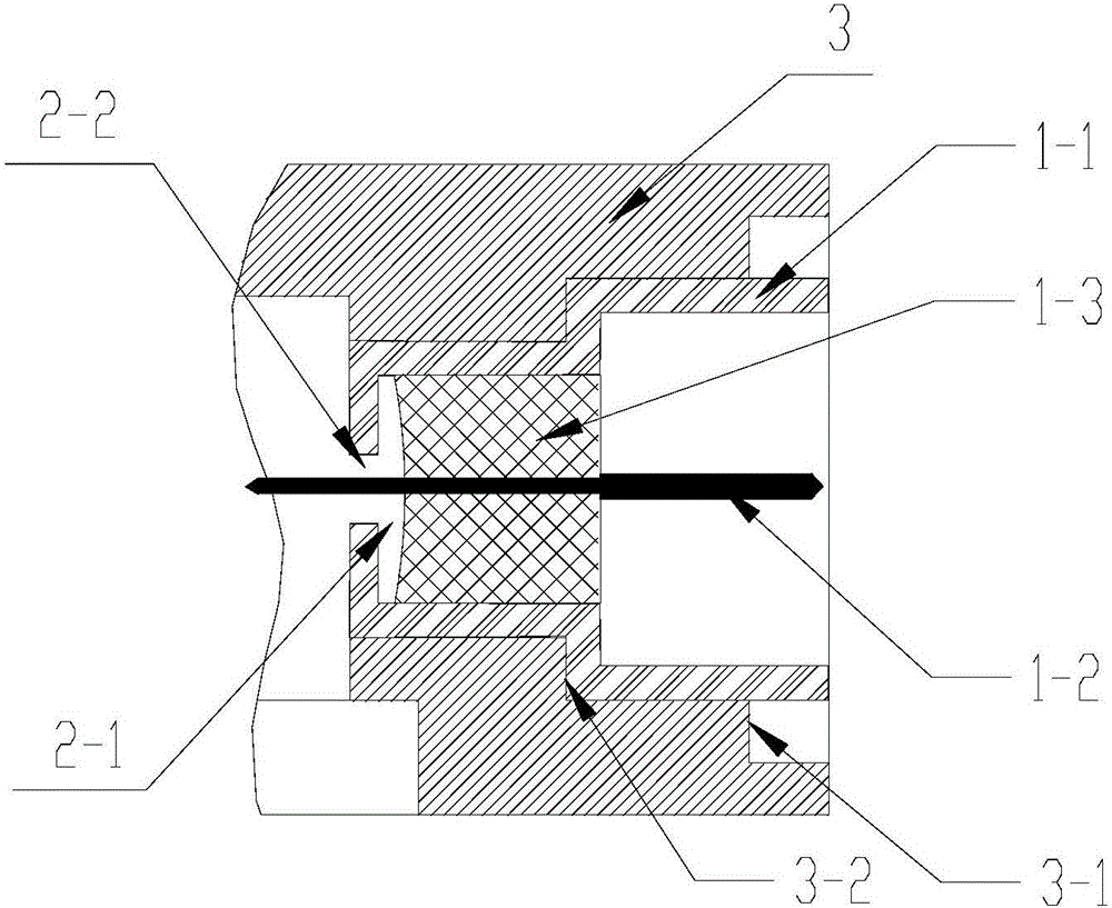
[0017] In Embodiment 2 of the present invention, the part of the air cavity structure originally in the mounting hole of the housing is processed to the end position of the end where the radio frequency coaxial connector 1 is connected to the microstrip line. Impedance matching structure The part extending from the outer conductor 1-1 of the connector and the insulator 1-3 form a first air cavity structure 2-1 with an inner diameter of 2 mm and a length of 0.15 mm. Refer to the attached Figure 4 . Compared with Embodiment 1, the installation hole 3 of the connector also needs to process a ferrule hole with a diameter of 0.6 mm and a thickness of 0.25 mm at the bottom of the installation hole to match. Fitting the connector and the solder ring into the mounting hole during soldering can also avoid the situation that the connector is not installed in place caused by the positioning of multiple step holes and the machined residual burrs or foreign objects on the step surface. I...
PUM
 Abstract
Description
Claims
Application Information
 - R&D
- Intellectual Property
- Life Sciences
- Materials
- Tech Scout
- Unparalleled Data Quality
- Higher Quality Content
- 60% Fewer Hallucinations
Browse by: Latest US Patents, China's latest patents, Technical Efficacy Thesaurus, Application Domain, Technology Topic, Popular Technical Reports.
© 2025 PatSnap. All rights reserved.Legal|Privacy policy|Modern Slavery Act Transparency Statement|Sitemap|About US| Contact US: help@patsnap.com


