Fabrication method of motor rotor assembly

A technology for motor rotors and manufacturing methods, which is applied in the direction of electric components, electrical components, and the manufacture of motor generators, etc., and can solve problems such as low affinity, low surface tension of coatings, and low bonding strength between annular magnetic steel and cylindrical mandrels, etc. problem, to achieve the effect of high affinity and high bonding strength

Active Publication Date: 2017-05-31
NINGBO YUNSHENG
View PDF7 Cites 0 Cited by
  • Summary
  • Abstract
  • Description
  • Claims
  • Application Information

AI Technical Summary

Problems solved by technology

[0004] However, the following problems exist in the manufacturing method of the existing motor rotor assembly: 1. The ring-shaped magnetic steel has been electroplated as a whole, the surface tension of the coating is low, and the affinity with the adhesive is very low, and the combination of the coating and the adhesive The force is low, after the bonding of the ring magnet and the cylindrical mandrel, the bonding strength of the ring magnet and the cylindrical mandrel is low, and the torque between the ring magnet and the cylindrical mandrel cannot meet the working requirements of the rotor assembly , during the operation of the motor, the annular magnetic steel and the cylindrical mandrel are easily separated and the motor is damaged; 2. When the cylindrical mandrel is inserted into the inner hole of the annular magnetic steel, it is coated on the inner hole wall of the annular magnetic steel The adhesive on the top or the outer wall of the cylindrical mandrel will be pushed to one end of the inner hole of the ring magnet as the cylindrical mandrel moves, thus causing the gap between the other end of the inner hole of the ring magnet and the cylindrical mandrel There is almost no adhesive to connect between them, the cylindrical mandrel will be suspended, and the effective bonding area between the annular magnetic steel and the cylindrical mandrel will be reduced. On the one hand, the rotor assembly will generate noise during high-speed rotation, and on the other hand On the one hand, the bonding strength between the ring magnet and the cylindrical mandrel decreases. During high-speed rotation, the ring magnet and the cylindrical mandrel are easily separated, resulting in damage to the motor.

Method used


Image

  • Fabrication method of motor rotor assembly
  • Fabrication method of motor rotor assembly
  • Fabrication method of motor rotor assembly

Examples


Embodiment 1

[0027] Embodiment one: if Figure 3-6 As shown, a method for manufacturing a motor rotor assembly includes the following steps:

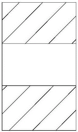
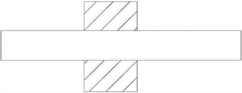
[0028] (1) Process the inner hole of the annular magnetic steel 1: the inner hole of the annular magnetic steel 1 is divided into a first inner hole 11 and a second inner hole 12, the diameter of the first inner hole 11 is denoted as D1, and the second inner hole The diameter of the hole 12 is marked as D2, the axial depth of the first inner hole 11 is marked as L1, the axial depth of the second inner hole 12 is marked as L2, the thickness of the ring magnetic steel 1 is marked as L, and the thickness of the cylindrical mandrel 2 is The outer diameter is recorded as D, D1 is 0.06mm larger than D, D2 is 0.2mm larger than D1, L=L1+L2, 1 / 3L≤L2≤1 / 2L;

[0029] (2) Electroplating is carried out to the annular magnet 1, and the electroplating layer is attached to the other surfaces of the annular magnet 1 except the inner surface after the electroplating;...

Embodiment 2

[0037] Embodiment two: if Figure 3-6 As shown, a method for manufacturing a motor rotor assembly includes the following steps:

[0038] (1) Process the inner hole of the annular magnetic steel 1: the inner hole of the annular magnetic steel 1 is divided into a first inner hole 11 and a second inner hole 12, the diameter of the first inner hole 11 is denoted as D1, and the second inner hole The diameter of the hole 12 is marked as D2, the axial depth of the first inner hole 11 is marked as L1, the axial depth of the second inner hole 12 is marked as L2, the thickness of the ring magnetic steel 1 is marked as L, and the thickness of the cylindrical mandrel 2 is The outer diameter is recorded as D, D1 is 0.06mm larger than D, D2 is 0.2mm larger than D1, L=L1+L2, 1 / 3L≤L2≤1 / 2L;

[0039] (2) Electroplating is carried out to the annular magnet 1, and the electroplating layer is attached to the other surfaces of the annular magnet 1 except the inner surface after the electroplating;...

Embodiment 3

[0048] Embodiment three: as Figure 3-6 As shown, a method for manufacturing a motor rotor assembly includes the following steps:

[0049] (1) Process the inner hole of the annular magnetic steel 1: the inner hole of the annular magnetic steel 1 is divided into a first inner hole 11 and a second inner hole 12, the diameter of the first inner hole 11 is denoted as D1, and the second inner hole The diameter of the hole 12 is marked as D2, the axial depth of the first inner hole 11 is marked as L1, the axial depth of the second inner hole 12 is marked as L2, the thickness of the ring magnetic steel 1 is marked as L, and the thickness of the cylindrical mandrel 2 is The outer diameter is recorded as D, D1 is 0.04mm larger than D, D2 is 0.1mm larger than D1, L=L1+L2, 1 / 3L≤L2≤1 / 2L;

[0050] (2) Electroplating is carried out to the annular magnet 1, and the electroplating layer is attached to the other surfaces of the annular magnet 1 except the inner surface after the electroplatin...


PUM


Abstract

The invention discloses a fabrication method of a motor rotor assembly. The fabrication method comprises the steps of firstly, processing an inner hole of annular magnetic steel; secondly, electroplating the annular magnetic steel, attaching electroplating layers onto other surfaces except an inner surface of the annular magnetic steel after being electroplated, and enabling an axial direction of the annular magnetic steel to be in a horizontal direction; thirdly, coating a layer of binding agent on the inner hole of the annular magnetic steel, inserting a cylindrical core shaft into the annular magnetic steel from a first inner hole, and then allowing the cylindrical core to extent out of a second inner hole; fourthly, rotating the annular magnetic steel by 90 degrees so that the axial of the annular magnetic steel is in a vertical direction, and encapsulating a gap between of the second inner hole and the cylindrical core shaft with the binding agent, wherein the second inner hole is arranged above the first inner hole; and finally, maintaining the position of the annular magnetic steel unchanged after the encapsulation of the binding agent is completed, and completing the fabrication of the motor rotor assembly after the binding agent is naturally cured. The fabrication method has the advantages that no noise is generated during the high-speed rotation process, the motor rotor assembly has relatively large twisting force, the annular magnetic steel cannot be separated from the cylindrical core shaft, and the service lifetime of the motor is prolonged.

Description

technical field [0001] The invention relates to a manufacturing method of a rotor assembly, in particular to a manufacturing method of a motor rotor assembly. Background technique [0002] With the continuous improvement and improvement of the performance of permanent magnet materials, especially the improvement of thermal stability and corrosion resistance of NdFeB permanent magnets and the further development and improvement of power electronic components, the application and development of rare earth permanent magnet motors have entered a new stage. stage. At present, rare earth permanent magnet motors are developing in the direction of high power (ultra-high speed) and high function (high temperature). As one of the important components of rare earth permanent magnet motors, the rotor assembly has higher and higher production requirements. [0003] The rotor assembly of the motor includes an annular magnetic steel and a cylindrical mandrel, and the cylindrical mandrel i...

Claims


Application Information

Patent Timeline
Patent Type & Authority Applications(China)
IPC IPC(8): H02K15/03H02K1/28
CPCH02K1/28H02K15/03
Inventor 阚荣金董
Owner NINGBO YUNSHENG
Why Eureka
Try Eureka